· Thomas Webb · Engineering · 10 min read
Liquid Cooling Compatible PCB Design for AI Data
Engineering guide for designing PCBs that survive immersion cooling environments in AI data centers. Covers material compatibility with dielectric fluids, thermal cycling reliability, solder mask chemical resistance, via fill requirements, and stackup considerations for 800W+ GPU server boards operating in single-phase and two-phase liquid cooling systems.
Quick Answer
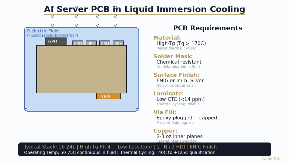
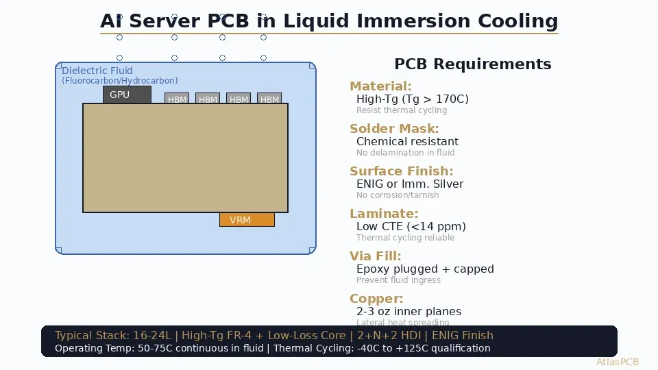
PCBs for liquid immersion cooling require High-Tg FR-4 (Tg 170C+) with low-CTE laminate, chemically resistant solder mask rated for fluorocarbon fluid exposure, ENIG or immersion silver surface finish, fully plugged and capped vias to prevent fluid ingress, and 2-3oz inner copper planes for lateral heat spreading. Standard FR-4 with OSP finish will fail within months in immersion cooling environments.
Quick Answer: Immersion Cooling PCB Requirements
| Requirement | Standard PCB | Immersion Cooling PCB |
|---|---|---|
| Laminate | FR-4 Tg135-150 | High-Tg FR-4 (Tg170+), low CTE |
| Moisture absorption | < 0.5% typical | Must be < 0.1% |
| Solder mask | Standard LPI | Chemical-resistant, fluid-rated |
| Surface finish | HASL/OSP/any | ENIG or Immersion Silver |
| Via structure | Tented or open | Epoxy-plugged + copper-capped |
| Copper weight (inner) | 1oz standard | 2-3oz for thermal spreading |
| Thermal cycling rating | -40C to +105C | -40C to +125C (1000+ cycles) |
| Layer count | 4-12 typical | 16-24 for AI server class |
Standard PCB materials and processes are insufficient for immersion cooling environments. Boards designed without these considerations fail through fluid absorption, via cracking, solder mask delamination, or copper fatigue within 6-18 months of deployment.
The Immersion Cooling Environment
Liquid immersion cooling submerges entire server boards in a bath of dielectric fluid — typically fluorocarbon-based (3M Novec, Solvay Galden) or synthetic hydrocarbon (Shell Immersol). The board operates continuously at 40-65C fluid temperature with component junction temperatures reaching 85-105C. During maintenance shutdowns, the board experiences thermal cycling from operating temperature to ambient (potentially sub-zero in some facilities).
This environment creates challenges that air-cooled boards never face. The dielectric fluid is in continuous contact with every surface of the PCB — including exposed laminate edges, via barrels, solder joints, and solder mask. Any material weakness that would be irrelevant in air becomes a failure mode in fluid. Micro-cracks in solder mask that would never cause problems in a conventional server become pathways for fluid ingress into the laminate structure.
The thermal cycling profile is also more aggressive than traditional air-cooled equipment. Air-cooled servers experience gradual temperature changes (1-3C per minute during startup). Immersion-cooled boards can see rapid thermal transitions during fluid circulation changes or maintenance operations — 10-20C per minute is common. This rapid cycling creates higher mechanical stress on solder joints, via barrels, and laminate interfaces.
The AI server market is driving this technology because GPU power consumption has exceeded what air cooling can handle. An NVIDIA H100 SXM module dissipates 700W; the upcoming B200 pushes beyond 1000W. At these power levels, immersion cooling provides 3-5x better thermal resistance than the best air-cooled heatsink solutions, enabling higher clock frequencies and longer sustained boost performance.
AI SERVER PCB FABRICATION
High-Layer-Count Boards for AI Infrastructure
We fabricate 16-30 layer boards with High-Tg materials, 2+N+2 HDI, and controlled impedance for GPU server and AI accelerator applications.
Get AI Board Quote ›
Material Selection for Fluid Compatibility
The laminate must resist fluid absorption over years of continuous submersion. Standard FR-4 absorbs 0.3-0.5% moisture by weight under IPC-TM-650 2.6.2.1 testing. While fluorocarbon fluids are not moisture, the same material porosity that allows water absorption also allows fluid absorption — and some dielectric fluids have lower surface tension than water, meaning they penetrate micro-pores more aggressively.
High-Tg laminates with dense resin systems offer the lowest absorption rates. Materials like Shengyi S1000-2M (Tg170, water absorption 0.09%), Isola 370HR (Tg180, absorption 0.12%), and ITEQ IT-180A (Tg175, absorption 0.10%) provide the combination of high glass transition temperature and low porosity needed for immersion cooling. These materials resist thermal decomposition at the elevated temperatures common in cooling fluid and maintain their mechanical properties through thousands of thermal cycles.
The Z-axis CTE (coefficient of thermal expansion) becomes critical in immersion cooling because the rapid thermal cycling amplifies the cumulative mechanical stress on plated through-holes. Standard FR-4 has Z-axis CTE of 50-70 ppm/C above Tg. High-performance laminates reduce this to 30-45 ppm/C, directly reducing the fatigue strain on via barrels during each thermal cycle. For a 20-layer board with 2mm total thickness, reducing Z-CTE from 60 to 35 ppm/C increases via fatigue life by approximately 3-4x.
Via Structure: The Fluid Ingress Problem
Open or tented vias in an immersion-cooled board create a hydraulic fatigue failure mode that has no equivalent in air-cooled systems. When the board heats up during operation, dielectric fluid trapped in the via barrel expands. If the via is sealed on both ends (by component pads or solder mask tenting), the expanding fluid creates internal pressure that stresses the copper barrel, pad connections, and surrounding laminate.
Over thousands of thermal cycles, this hydraulic stress causes barrel cracking, pad lifting, and localized delamination. The solution is to eliminate trapped fluid volumes by specifying fully epoxy-plugged vias with copper cap plating. The IPC-4761 Type VII fill (conductive or non-conductive epoxy fill with cap plating) leaves no internal void for fluid to enter.
For HDI designs with blind and buried microvias, the challenge is amplified because microvias create small but high-pressure sealed volumes. Every microvia must be completely filled during the buildup process — no voids, no dimples, no partial fills. Cross-section quality control becomes essential, with 100% X-ray inspection recommended for immersion-cooling-destined boards to verify fill completeness before shipping.
The cost impact of via plugging is moderate — typically adding $1-3 per board at production volumes for full epoxy fill and cap plating. This is a trivial cost relative to the server board value ($200-500) and the cost of a field failure in a $50,000+ GPU server.
HDI WITH VIA-IN-PAD
Fully Plugged Vias for High-Reliability Applications
IPC-4761 Type VII via fill with copper cap plating. 100% X-ray inspection available for critical boards destined for immersion cooling environments.
Get HDI Quote ›Solder Mask and Surface Finish Considerations
The solder mask in an immersion-cooled board must resist chemical interaction with dielectric fluid for 5-10 years of continuous exposure. Standard LPI (liquid photoimageable) solder masks are formulated for air environments and may soften, swell, or delaminate in certain dielectric fluids — particularly hydrocarbon-based fluids that have higher solvency than fluorocarbons.
Fluorocarbon fluids (Novec 7100, 7200; Galden HT-series) are generally compatible with standard epoxy-based solder masks, though long-term testing at elevated temperature (60C+ continuous) should be validated for the specific fluid-mask combination. Hydrocarbon fluids require more careful material selection — some mask formulations will absorb hydrocarbon molecules and swell over time, losing adhesion to the laminate.
For surface finish, ENIG provides the most robust protection because the nickel barrier layer prevents copper diffusion into the gold surface and resists all common dielectric fluids. Immersion silver is also acceptable — silver is chemically inert in fluorocarbon environments — but may tarnish in hydrocarbon fluids containing sulfur compounds. HASL provides adequate protection but the uneven surface topology can trap micro-bubbles during initial fluid fill, creating localized hotspots.
OSP (organic solderability preservative) should be avoided entirely for immersion cooling applications. The organic coating dissolves in most dielectric fluids within hours to days, leaving bare copper exposed. Copper in contact with dielectric fluid at elevated temperature will develop oxide formations that compromise solder joint reliability if the board ever requires rework.
Stackup Design for Thermal Performance
In immersion cooling, the PCB itself becomes part of the thermal management system. Unlike air-cooled designs where a heatsink handles the majority of heat removal, immersion-cooled boards transfer heat from component junctions through the PCB stackup directly into the surrounding fluid. This changes how you think about inner-layer copper.
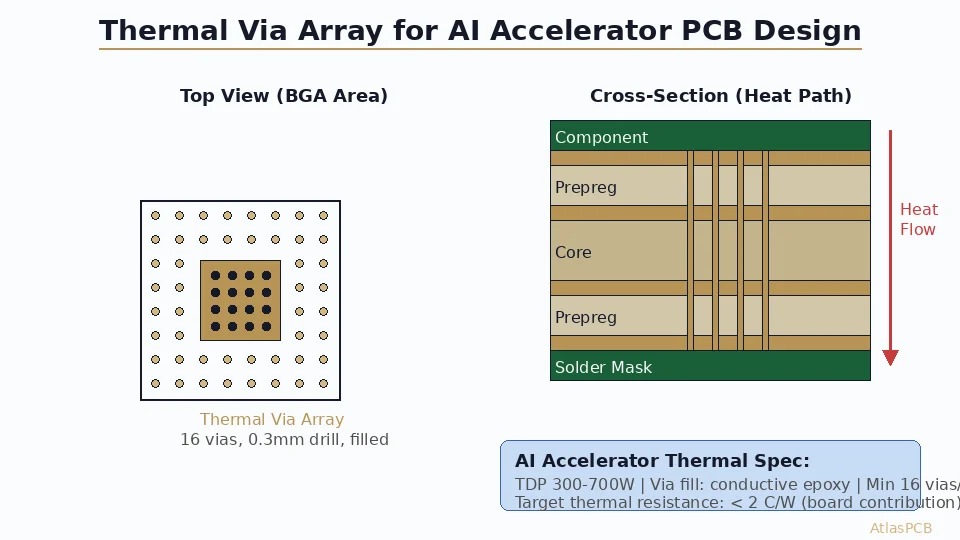
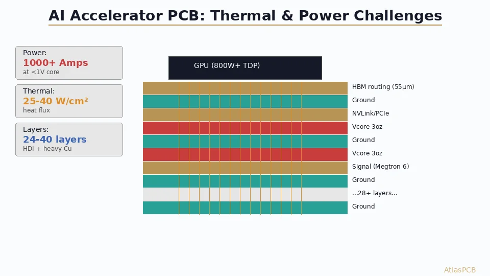
Heavy inner-plane copper (2oz or 3oz) serves dual purpose in immersion-cooled AI server boards: electrical power delivery for 200-1000A total GPU current, and lateral heat spreading that distributes thermal energy across a larger board surface area exposed to fluid. A 2oz copper plane has 70um thickness — 2x the thermal conductivity cross-section of standard 1oz copper. For GPU power delivery zones where 500A+ flows through the PCB, 3oz inner copper is common.
The stackup architecture for a typical AI server board follows a pattern: 2+N+2 or 3+N+3 HDI buildup with High-Tg FR-4 core, low-loss prepreg for 112G SerDes layers, and heavy copper on power planes. A representative 20-layer stackup might look like: 2 HDI signal layers (75um trace), 4 high-speed routing layers (controlled impedance), 8 power/ground planes (2-3oz copper), 4 additional signal layers, and 2 bottom HDI layers.
The total board thickness for these stackups typically runs 2.5-3.5mm — thicker than standard boards due to the heavy copper planes. This thickness creates high aspect ratio challenges for through-hole vias (0.3mm via through 3.0mm board = 10:1 ratio), pushing designs toward HDI architectures where microvias handle layer transitions on the outer buildup and only a few mechanical vias traverse the full stackup.
ADVANCED STACKUP ENGINEERING
20+ Layer HDI Boards with Heavy Copper Power Planes
Up to 30 layers, 3oz inner copper, 2+N+2 HDI buildup, controlled impedance on all signal layers. Built for AI server applications.
Reliability Qualification and Testing
Before deploying PCBs in production immersion cooling systems, reliability qualification should include: thermal cycling testing per IPC-9701 (1000 cycles minimum at -40C to +125C), fluid immersion aging (1000 hours at max operating temperature in the specific fluid), microsection analysis of via barrels after aging, and peel strength testing of solder mask after fluid exposure.
The IPC-6012ES (space and defense addendum) specification provides a useful framework for qualification testing, as its requirements for via reliability and thermal cycling closely match what immersion cooling demands. Even if your boards are destined for commercial data centers rather than space applications, the Class 3 reliability testing methodology ensures your boards will survive the demanding thermal environment.
Particular attention should be paid to CAF (conductive anodic filament) resistance in immersion cooling environments. The combination of electrical bias, elevated temperature, and potential micro-moisture at laminate interfaces creates conditions favorable to CAF growth. High-CAF-resistance laminates and adequate clearances between vias and traces (minimum 0.5mm for 48V power systems) are essential design rules for immersion-cooled boards.
ATLASPCB
Building AI Infrastructure? Start with the Right PCB
High-Tg materials, heavy copper, HDI microvias, ENIG finish — all standard capabilities. From prototype to production volumes for AI server boards.
Upload Your AI Board Design ›
Related Reading:
About AtlasPCB — We specialize in complex PCB manufacturing for HDI, RF, and high-reliability applications. Explore our aluminum and metal-core PCB services . Every order includes free engineering review. Get your quote.
Reviewed by AtlasPCB Engineering Team — IPC-certified manufacturing specialists with 15+ years of production experience in HDI, RF, and high-reliability PCB fabrication. Content based on factory floor data and real customer design reviews.
Frequently Asked Questions
Can standard FR-4 PCBs survive liquid immersion cooling?
What surface finish works best in liquid cooling?
Why do vias need to be plugged for immersion cooling?
What is the typical PCB layer count for AI GPU server boards?
- pcb
- ai-hardware
- liquid-cooling
- data-center
- thermal-management