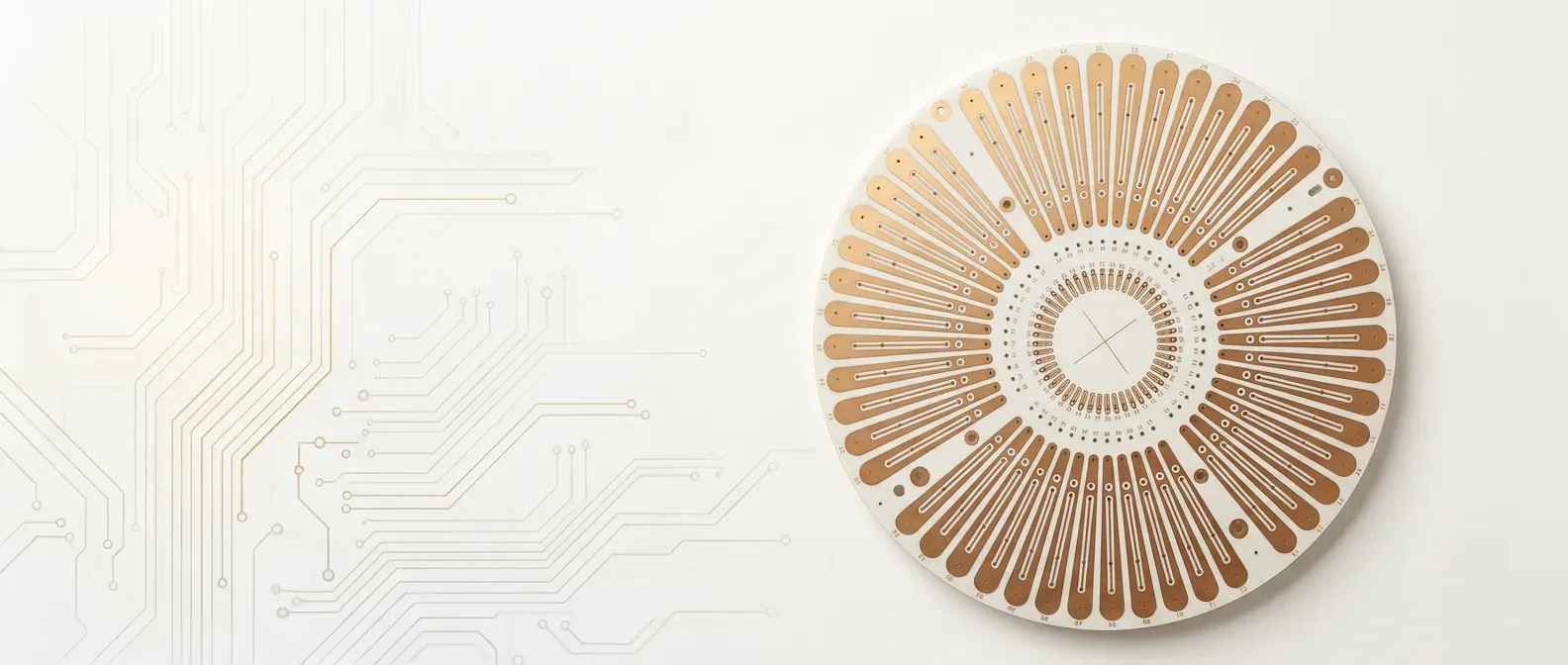
RF & High-Frequency PCBs
RF PCB Manufacturer Rogers & PTFE for DC to 77GHz
Purpose-built for signal integrity. RO4350B with Df 0.0037. Six PTFE options down to Dk 2.20. ±8% impedance on every build.
At a Glance
Material Options
The Right Substrate for Your Frequency
Three Rogers configurations and six PTFE materials — each selected for specific performance bands.
Pure Rogers
All layers on RO4350B. Dk 3.48, Df 0.0037 @ 10GHz. Maximum consistency across the full stackup. Up to 12 layers.
Rogers + FR-4 Hybrid
RF signal on Rogers, digital/power on FR-4. 40-60% cost savings vs pure. Available in single-sheet or double-sheet configurations.
PTFE Teflon
Six substrate options from Dk 2.20 to Dk 3.50. Ultra-low loss for mmWave. Available in 2 and 4 layer configurations. Specialized processing for PTFE bonding and plating adhesion.
Rogers RO4350B
Industry-Standard RF Laminate
Proven Performance to 40GHz
Our RF-qualified factory maintains Rogers material certification and verifies Dk batch-to-batch for consistent production impedance.Dielectric Performance
Dk 3.48 ±0.05, Df 0.0037 @ 10GHz. Stable to 40GHz+ with minimal frequency dispersion.
Three Configurations
Pure (2-12L), Single Hybrid with 1 Rogers sheet (4-12L), Double Hybrid with 2 Rogers sheets (6-12L).
Process Compatible
Rogers RO4350B processes on standard FR-4 equipment — no special PTFE handling needed. Shorter lead times and lower cost than traditional PTFE.
Hybrid Advantage
Put your RF critical layer on Rogers, route digital on low-cost FR-4. Get the performance where it matters without paying for it everywhere.
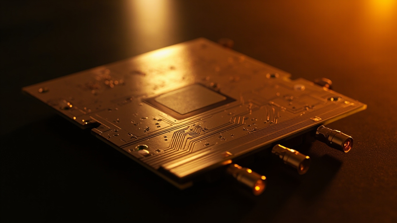
PTFE Substrates
Ultra-Low Loss for mmWave
Six PTFE Options
PTFE requires specialized plasma treatment, sodium etch for adhesion, and controlled lamination pressure. Our PTFE-certified factory handles this daily. Available in 2 and 4 layer configurations only.Dk 2.20 (F4BME220)
Lowest dielectric constant. For 60-77GHz automotive radar and V-band communications.
Dk 2.65 (F4BM-2)
Standard PTFE with excellent Df. Available copper-clad or unclad for bonding.
Dk 3.38-3.50 (WL-CT338 / S7136H)
Cost-optimized PTFE alternatives. S7136H at ¥0.069/cm² — lowest cost PTFE option.
Specialized (SJ9294)
Dk 2.94 with buried resistor capability. For integrated passive designs.
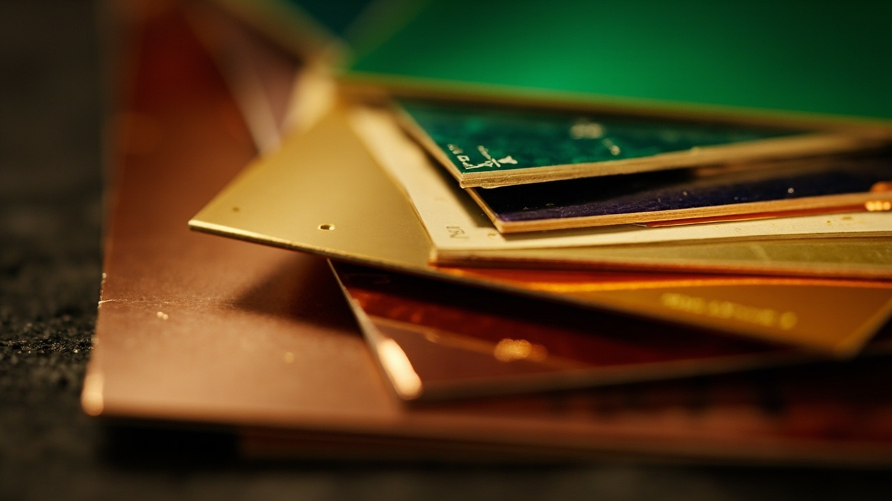
Material Selection
RF PCB Manufacturer — Frequency & Material Selection
As an RF PCB manufacturer, we match every RF circuit board to its operating band before it reaches the floor. The guidance below mirrors the Dk figures listed above — use it to choose between a Rogers stackup and a PTFE PCB build for your telecom, 5G, or mmWave design.
| Frequency Band | Recommended Material | Why It Fits |
|---|---|---|
| Sub-6 GHz (5G / telecom) | Rogers RO4350B — Dk 3.48, Df 0.0037 | Process-compatible with FR-4 equipment for lower cost and faster turnaround. |
| 6–40 GHz microwave | Rogers RO4350B (pure or hybrid) | Stable to 40GHz+ with minimal frequency dispersion. |
| mmWave 40–77 GHz (V-band / automotive radar) | PTFE — Dk 2.20 (F4BME220) | Ultra-low loss for 60–77GHz automotive radar and V-band links. |
For a sub-6 GHz telecom PCB or 5G base-station radio, a Rogers RO4350B RF circuit board is usually the most cost-effective path — see our Rogers PCB capabilities for pure and hybrid stackups. When your design pushes past 40GHz into mmWave, a PTFE PCB on Dk 2.20 laminate keeps insertion loss low all the way to 77GHz.
Materials & Performance
RF PCB Materials & Performance Data
Substrate Properties and Selection Criteria
Rogers RO4350B is our highest-volume RF laminate and for good reason. At 10GHz, it delivers Dk 3.48 with ±0.05 tolerance lot-to-lot, and Df of 0.0037. The CTE is 14 ppm/°C in the X-Y plane (matched to copper at 17 ppm), which means solder joints survive thermal cycling without cracking from differential expansion. RO4350B is thermoset — it processes on standard FR-4 press and drill equipment without the special handling PTFE demands. It carries UL94 V-0 flame rating, which matters for any product going through safety certification. For most applications below 20GHz, RO4350B provides the best balance of electrical performance, processability, and cost.
Rogers RO4003C offers lower loss than RO4350B: Dk 3.38 ±0.05 at 10GHz with Df of 0.0027 — a 27% reduction in loss tangent. The tradeoff is UL94 HB flame rating (horizontal burn only, not V-0), which disqualifies it from some consumer electronics and telecom enclosure applications without additional fire protection. CTE matches RO4350B at 14 ppm/°C. We recommend RO4003C when your link budget is tight (long trace runs, power-sensitive receivers) and your product can accept HB rating or when the PCB sits inside a metal enclosure that provides fire containment.
PTFE substrates become necessary above 24GHz where hydrocarbon-based laminates (Rogers 4000 series) show increasing frequency dispersion. Our PTFE portfolio covers a range of dielectric constants: F4BM2 at Dk 2.65 is the general-purpose PTFE with good dimensional stability and well-characterized processing. Taconic TLY-5 at Dk 2.20 provides the lowest loss for V-band (60GHz) and automotive radar (77GHz) applications — the lower Dk means wider traces for the same impedance, which relaxes fabrication tolerances at millimeter-wave frequencies. Arlon DiClad 880 at Dk 2.17 is the lowest Dk material we stock, used for specialized radar and satellite applications where every 0.01 dB/cm of insertion loss matters.
The frequency threshold for material selection follows practical engineering rules we have validated across hundreds of RF builds. Below 6GHz, RO4350B is sufficient for nearly every application — the loss tangent at these frequencies contributes minimal insertion loss over typical trace lengths (under 0.02 dB/cm at 5GHz on a 50-ohm microstrip). Between 6GHz and 24GHz, RO4350B still works for short traces (under 3 inches), but traces longer than 4 inches at 15GHz+ start showing meaningful loss differences versus PTFE. Above 24GHz, PTFE is mandatory: at 28GHz, a 10cm RO4350B trace accumulates 1.2 dB loss versus 0.6 dB on PTFE Dk 2.2 — that 0.6 dB difference directly reduces your receiver sensitivity or forces higher transmit power.
Hybrid stackups represent our most cost-effective approach for boards mixing RF and digital functions. The typical configuration places Rogers or PTFE on the outer layers (where microstrip RF traces run) with standard FR-4 cores for inner power planes, ground planes, and digital routing layers. A 6-layer hybrid might be: Rogers L1 / prepreg bond / FR-4 Ground / FR-4 core / FR-4 Power / prepreg bond / Rogers L6. This structure saves 40-60% compared to all-Rogers construction while delivering identical RF performance on the signal layers. The bonding prepreg between Rogers and FR-4 requires specific materials — we use Rogers 4450F bondply or Taconic FR-27 — to ensure reliable adhesion and controlled impedance at the transition between materials.
Impedance accuracy on RF boards is tighter than standard digital work. Our standard ±8% applies to all builds, but for critical RF applications (filters, couplers, matching networks) we offer ±5% on request. Achieving ±5% requires material pre-screening (we measure incoming laminate Dk with a resonant cavity method before production), tighter etch controls (±0.3mil trace width tolerance versus ±0.5mil standard), and 100% TDR testing of every trace — not just coupons. The cost premium is 15-20% above standard RF pricing, but for a bandpass filter where 50-ohm lines must hit 50±2.5 ohms, that premium is far cheaper than post-fabrication tuning or board respins.
Dk characterization before production is standard procedure on critical builds. We receive material from our laminate suppliers with published Dk values, but actual Dk varies ±1-2% between manufacturing lots. For applications where Dk variation directly impacts center frequency (filters, delay lines, antenna feed networks), we measure the incoming material lot using a split-post dielectric resonator at 10GHz. This gives us actual Dk to ±0.02 accuracy, which we feed back into our impedance modeling. The result: your traces are designed for the material we actually have on the floor, not the datasheet nominal. This step adds 1-2 days to lead time but eliminates the need for iterative prototyping on frequency-sensitive circuits.
Applications
Where Our RF Boards Work
5G & mmWave
Antenna arrays, beamforming networks, 24-77GHz automotive radar front-ends.
Satellite & Space
Low-noise amplifiers, frequency converters, phased array feeds.
Radar Systems
T/R modules, IF processing, signal conditioning for defense and automotive.
Test & Measurement
VNA calibration substrates, signal generator output stages, spectrum analyzer front-ends.
Medical RF
MRI surface coils, RF ablation controllers, wireless implant telemetry.
IoT Wireless
WiFi 6E/7 modules, UWB ranging, LoRa front-ends where insertion loss matters.
FAQ
RF PCB Questions
Rogers vs PTFE — which should I use?
Rogers RO4350B: for most applications up to 40GHz. Process-compatible with FR-4 equipment, lower cost, faster turnaround. PTFE: when you need Dk below 3.0 or operation above 40GHz.
Pure Rogers vs Hybrid?
Hybrid saves 40-60% if only one signal layer needs low-loss performance. Pure when every layer carries RF signals (e.g., stripline filters, coupled-line structures).
What impedance tolerance can you achieve?
±8% standard on all RF builds with TDR verification. Every RF order ships with an impedance test report.
What is the maximum frequency you support?
77GHz, proven in production automotive radar builds. For mmWave applications above 40GHz, we use PTFE substrates with Dk below 2.5 combined with process controls for surface roughness (RTF copper, controlled etch profiles). We have shipped 60GHz V-band and 77GHz radar boards in volume.
Can I get Rogers on just one layer?
Yes — hybrid stackups are our specialty and the most popular configuration we build. Place Rogers or PTFE on the RF signal layers only, with standard FR-4 for power planes, ground planes, and digital routing layers. A 6-layer board with two Rogers outer layers and FR-4 inner core saves 40-60% compared to all-Rogers construction, with identical RF performance on the signal layers that matter.
How do you control surface roughness for mmWave?
We specify RTF (Reverse Treat Foil) copper with Ra below 0.3μm for frequencies above 20GHz. Standard ED (electrodeposited) copper with Ra around 1.5-2.0μm works fine below 10GHz, but above 20GHz the skin depth drops below the roughness peaks and conductor loss increases sharply. For 77GHz radar boards, we use HVLP (Hyper Very Low Profile) foil and verify roughness on incoming material with a profilometer. We select the foil type based on your operating frequency and total loss budget.
Building at RF?
Select your substrate and configuration online. Instant quote with material confirmation.
Resources
RF & High-Frequency Engineering Guides
Material selection, cost analysis, and design best practices for RF PCBs.
RF PCB Cost Breakdown: Rogers, PTFE, and Hybrid Stackup Pricing
Real cost multipliers and optimization strategies for RF board manufacturing.
High-Frequency PCB Design Best Practices
RF/microwave layout rules including ground planes, via fencing, and transition design.
Rogers vs PTFE for Automotive Radar at 77 GHz
Performance comparison of Rogers and PTFE substrates for automotive radar applications.
Isola 370HR vs Panasonic Megtron 4: Mid-Loss Laminate Selection
Practical comparison for mid-speed digital designs covering Dk/Df and thermal reliability.
Controlled Impedance PCB Pricing and Cost Optimization
How to specify impedance without paying premium pricing unnecessarily.
Copper Roughness and High-Speed Signal Loss Above 10 GHz
How foil profile affects insertion loss and what to specify for RF performance.