· Marcus Lin · Engineering · 8 min read
RF PCB Cost Breakdown: Rogers Ptfe
Understand what drives RF PCB manufacturing costs. Compare Rogers RO4350B, RO4003C, PTFE, and FR-4 hybrid stackup pricing with real cost multipliers, optimization strategies, and quotes.
Quick Answer
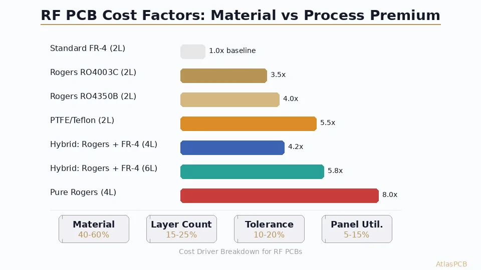
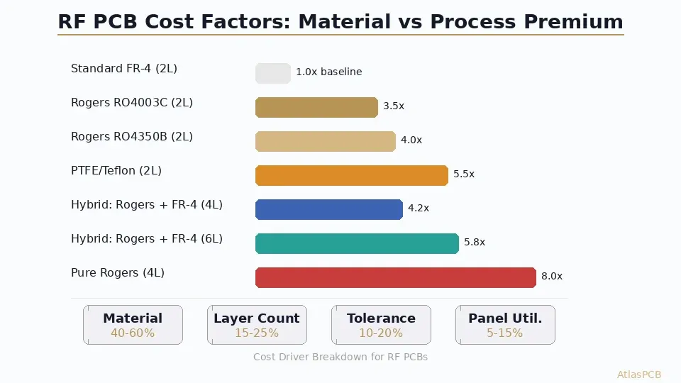
RF PCB costs run 3.5-8x more than equivalent FR-4 boards depending on material choice and construction. Rogers RO4003C is the most cost-effective RF laminate at 3.5x standard FR-4 pricing. Rogers RO4350B costs 4.0x. Pure PTFE (Teflon) runs 5-6x. The most cost-optimized approach for mixed-signal designs is a hybrid stackup using Rogers for RF layers bonded to FR-4 for digital/power layers, which typically costs 4-6x FR-4 depending on layer count. Material accounts for 40-60% of RF PCB total cost versus 20-30% for standard boards.
RF PCB Pricing at a Glance
| Configuration | Cost vs FR-4 | Typical 5pc Prototype (100x100mm) | Best For |
|---|---|---|---|
| Standard FR-4 (2L) | 1.0x | $30-50 | Digital only, < 1 GHz |
| Rogers RO4003C (2L) | 3.5x | $120-180 | RF up to 10 GHz, cost-sensitive |
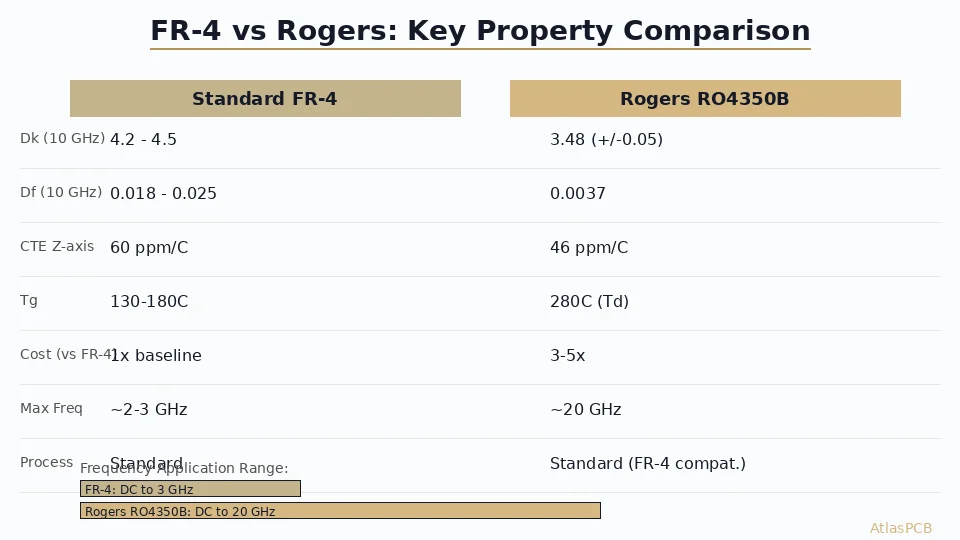
| Rogers RO4350B (2L) | 4.0x | $150-220 | RF up to 20 GHz, tighter Df |
| PTFE/Woven Glass (2L) | 5.5x | $200-300 | Microwave 20-77 GHz |
| Hybrid: Rogers + FR-4 (4L) | 4.2x | $350-500 | Mixed-signal with RF front-end |
| Hybrid: Rogers + FR-4 (6L) | 5.8x | $550-800 | Complex RF + digital integration |
| Pure Rogers (4L) | 8.0x | $700-1100 | All-RF system, phased array |
These prices assume standard tolerances, ENIG finish, and 5-day lead time. Tighter impedance tolerance (+/-3%) adds 15-20%. Controlled Dk specification adds 10%.
Understanding What Drives RF PCB Cost
The cost structure of an RF PCB differs fundamentally from a standard digital board because the material dominates the bill rather than the processing. On a typical FR-4 multilayer board, raw material represents 20-30% of fabrication cost, with the balance split among drilling, imaging, plating, and testing. On an RF board, material can represent 40-60% of total cost—sometimes more for pure Rogers or PTFE constructions with specialized prepreg.
This shift happens because Rogers and PTFE laminates cost 10-20x more per square meter than commodity FR-4. A standard 18x24-inch panel of 1.5mm FR-4 costs roughly $15-25 from major CCL suppliers. The same panel size in Rogers RO4350B costs $250-400. When your fabricator cuts your 100x100mm prototype from that panel, material waste alone can exceed the total cost of an equivalent FR-4 board—particularly if your board dimensions don’t panelize efficiently within the standard laminate sheet size.
Beyond raw material, RF boards incur processing premiums at nearly every fabrication step. PTFE materials require modified drill parameters (lower RPM, pecking cycles, specialized carbide bits) because the soft, gummy resin tends to smear rather than chip cleanly. Surface preparation for plating adhesion on PTFE requires plasma treatment or chemical sodium etch—an extra process step that adds cost and cycle time. Lamination of hybrid stackups demands precise temperature profiling to bond dissimilar materials without delaminating or warping. Each of these steps contributes to the cost multiplier.
RF PCB SPECIALISTS
Get an Accurate RF PCB Quote in 24 Hours
Upload your design with stackup requirements. We stock Rogers RO4003C, RO4350B, and offer hybrid stackups with FR-4 for cost optimization.
Compare RF Pricing ›
Material Selection: Balancing Performance Against Budget
The choice between Rogers variants, PTFE, and hybrid constructions should be driven by your operating frequency, loss budget, and volume economics—not habit or conservatism. Many designs specify pure Rogers when a hybrid stackup would deliver identical RF performance at 40-50% lower board cost.
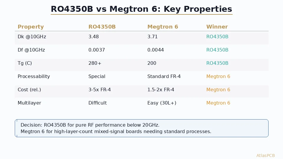
Rogers RO4003C (Dk 3.38, Df 0.0027 @ 10 GHz) is the workhorse material for RF designs up to 10 GHz. It processes similarly to FR-4 (thermoset resin, compatible with standard drill bits and lamination cycles), making it the least expensive Rogers option. The manufacturing familiarity means fewer yield hits and wider fabricator availability. For WiFi (2.4/5/6 GHz), sub-6 GHz 5G, GPS, and Bluetooth applications, RO4003C provides excellent Dk stability without the processing penalties of PTFE.
Rogers RO4350B (Dk 3.48, Df 0.0037 @ 10 GHz) costs 10-15% more than RO4003C and offers slightly tighter Dk tolerance (+/-0.05 vs +/-0.05 specified but often wider in practice for RO4003C). The ceramic filler provides better dimensional stability during thermal excursions. Specify RO4350B when you need characterized Dk tolerance at the PCB level for impedance-critical filter designs, or when operating in the 10-20 GHz range where the Df difference between RO4003C and RO4350B becomes measurable in link budgets.
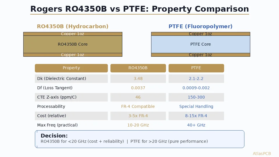
PTFE-based materials (Rogers RT/Duroid series, Taconic, Arlon) target applications above 20 GHz where the ceramic-filled hydrocarbon resin systems reach their loss limits. PTFE achieves Df values below 0.001 at millimeter-wave frequencies, enabling 77 GHz automotive radar, 60 GHz V-band links, and satellite Ku/Ka-band applications. The processing penalty is severe: PTFE requires plasma treatment for copper adhesion, specialized drilling to prevent smearing, and modified lamination profiles. These factors push cost to 5-6x FR-4 for 2-layer and compound aggressively with layer count.
The hybrid cost optimization: For a mixed-signal design with an RF front-end and a digital baseband, placing Rogers on the outer layer(s) where RF traces route and using FR-4 for inner power/ground planes and digital routing layers eliminates 50-60% of the premium material. The RF performance is identical because microstrip and stripline transmission lines interact primarily with the dielectric within 3-4 trace widths of the conductor—the FR-4 core buried layers away from RF traces contribute negligible loss.
Cost Optimization Strategies That Actually Work
Strategy 1: Hybrid stackup with Rogers outer / FR-4 inner — This single change provides the largest cost reduction for mixed-signal designs. A 6-layer all-Rogers board costs 10-12x FR-4. The same design with Rogers L1/L2 and FR-4 L3-L6 costs 5-6x—saving 40-50% with no measurable RF performance impact for traces on layers 1-2.
Strategy 2: Panel utilization optimization — Rogers laminates come in fixed sheet sizes (typically 12x18” or 18x24”). Your board dimensions determine how many pieces fit per panel. A 95x95mm board yields 4 pieces from a 12x18” panel. Reduce to 90x90mm and you might fit 6 pieces. That 5mm reduction can drop per-piece material cost by 33%. Ask your fabricator about panel utilization before finalizing board outline.
Strategy 3: RO4003C instead of RO4350B for < 10 GHz — Unless you need the tighter Dk tolerance of RO4350B for a narrowband filter, RO4003C performs identically at sub-10 GHz frequencies and costs 10-15% less. It also processes faster (no ceramic filler drilling issues), improving yield and reducing lead time.
Strategy 4: Standard thickness Rogers from stock — Fabricators stock common Rogers thicknesses (10, 20, 30, 60 mil). Non-standard thicknesses require minimum order quantities from Rogers Corporation, adding 2-3 weeks lead time and eliminating volume discounts. Design your stackup around stocked thicknesses whenever possible.
Strategy 5: Controlled impedance specification tolerance — Standard impedance tolerance is +/-10%. RF designs often require +/-5% or +/-3%. Each step tighter increases yield loss and cost. If your design can tolerate +/-7% (which many link budgets can), specify that rather than reflexively requesting +/-5%.
HYBRID STACKUP EXPERTS
Rogers + FR-4 Hybrid: Same RF Performance, Lower Cost
We optimize hybrid stackups for your frequency and layer count. Rogers RO4003C and RO4350B in stock for fast turns.
Volume Pricing Curves: When RF PCBs Become Affordable
The cost multiplier quoted above (3.5-8x) applies to prototype quantities of 5-25 pieces. At production volumes, the multiplier compresses significantly because material waste decreases, setup costs amortize, and fabricators optimize panel utilization.
For a typical 4-layer hybrid Rogers/FR-4 board (100x60mm):
- 5 pieces: $80-120 each (prototype pricing, high material waste)
- 50 pieces: $35-55 each (production panel, better utilization)
- 250 pieces: $20-35 each (volume material pricing kicks in)
- 1000+ pieces: $12-22 each (optimized panel, bulk Rogers discount)
The cost curve for RF PCBs is steeper than FR-4 because the fixed costs (material minimums, panel setup, impedance test coupons) represent a larger fraction of the prototype cost. At volume, these fixed costs become negligible and the per-piece price approaches raw material + processing, which is fundamentally 2-3x FR-4 rather than the 4-8x seen at prototype quantities.
For engineers budgeting an RF hardware program, the prototype-to-production cost ratio for RF boards is typically 5-8x, versus 2-3x for standard FR-4 boards. Plan your prototype budget accordingly.
Hidden Costs to Watch For
Several cost drivers in RF PCB fabrication are not immediately obvious from the laminate datasheet:
Impedance test coupons consume panel real estate. RF boards require dedicated test coupons (often 2-3 per panel) that are measured with TDR or VNA before shipping. These coupons eat board positions on the panel, reducing your yield per panel by 10-15%.
Edge plating for RF shielding adds a secondary plating process. If your design requires plated board edges for EMI containment or cavity shielding, expect 15-25% cost adder.
Via fencing around transmission lines increases drill count significantly. A single coplanar waveguide trace with proper via fencing can require 50-100 additional vias per centimeter of trace length. High drill counts on PTFE materials (which require slower drilling) compound cost.
Controlled Dk Rogers specification — Rogers offers standard tolerance (+/-0.05 on Dk) and “Design” tolerance (tighter, per request). The tighter specification requires Rogers to bin their production, adding lead time and 15-20% material premium.
ATLASPCB
Get Your RF PCB Quoted — No Guesswork on Pricing
Upload Gerbers with your material and impedance requirements. Detailed line-item quote showing material, processing, and testing costs separately.
Upload for RF Quote ›
Related Reading:
About AtlasPCB — We specialize in complex PCB manufacturing for HDI, RF, and high-reliability applications. Explore our RF and high-frequency PCB services, Rogers RO4350B PCB manufacturing, or get an multilayer PCB fabrication up to 30 layers . Every order includes free engineering review. Get your quote.
Reviewed by AtlasPCB Engineering Team — IPC-certified manufacturing specialists with 15+ years of production experience in HDI, RF, and high-reliability PCB fabrication. Content based on factory floor data and real customer design reviews.
Frequently Asked Questions
Why are RF PCBs so much more expensive than standard FR-4?
Is a hybrid Rogers/FR-4 stackup cheaper than all-Rogers?
What is the minimum order that makes RF PCB prototype pricing reasonable?
Can I get RF PCBs on quick-turn lead times?
- RF PCB
- Rogers
- PTFE
- PCB cost
- high-frequency
- hybrid stackup
- microwave PCB
- pricing