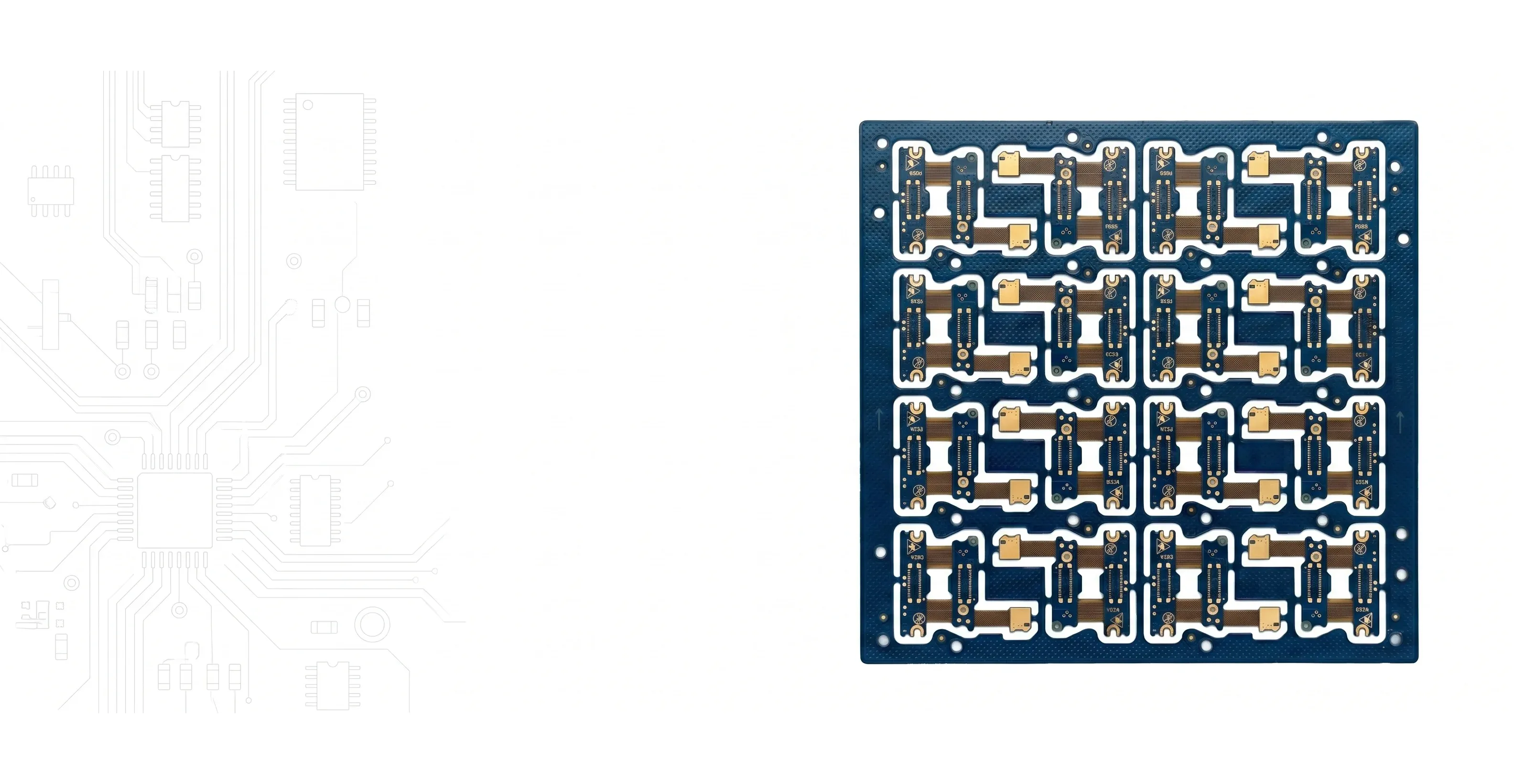
Rigid-Flex PCBs
Rigid-Flex PCB Manufacturer Eliminate Connectors. Gain Reliability.
Integrated rigid and flex in one assembly. Up to 22 layers. Dynamic bend rated for 500K+ cycles. No more FPC connectors to fail.
At a Glance
The Case for Rigid-Flex
Why Integrate Instead of Connect
Every connector you eliminate is a failure point removed and assembly step saved.
Zero Connector Failures
FPC connectors are the #1 field failure point in portable electronics. Integrated flex connections have no mating cycle wear, no contact resistance drift, no latch fatigue.
3D Folding Architecture
Fold your board into the product enclosure. Rigid sections carry components, flex sections bridge between them. Dramatically reduces assembly volume.
Dynamic Motion Applications
Laptop hinges, folding phones, robotic joints, print heads. Polyimide flex rated for 500K+ bend cycles with proper design rules.
Signal Integrity Through Flex
Controlled impedance maintained through the flex zone. No connector impedance discontinuities, no stub effects, no additional signal path length.
Our Capability
Rigid-Flex Engineering Expertise
Engineered for Flex Reliability
Rigid-flex is our most engineering-intensive product. Every order receives dedicated stackup review for bend feasibility and long-term reliability.Bend Radius Verification
We calculate minimum bend radius based on your layer count, copper thickness, and flex zone width. No guessing — verified before production.
Layer Transition Design
Critical rigid-to-flex transitions engineered for stress relief. Proper anchoring, stiffener placement, and coverlay termination.
Material Selection
Polyimide substrate (25μm/50μm) with polyimide coverlay. Adhesiveless options for high-reliability. FR-4 TG170 for rigid sections.
Dynamic vs Static Optimization
Different design rules for flex that bends once (static) vs repeatedly (dynamic). Trace routing, copper annulus, and via keep-out zones all adapted.

Applications
Where Rigid-Flex Excels
Trusted in Critical Systems
When the flex zone connects life-support electronics or guides a missile, manufacturing quality isn't optional.Consumer Electronics
Smartphones, smartwatches, AR/VR headsets, folding devices, action cameras — anywhere space is measured in fractions of a millimeter.
Medical Devices
Hearing aids, pacemaker leads, endoscope tips, surgical robots. Biocompatible materials available for implantable applications.
Aerospace & Defense
Missile guidance, satellite payloads, avionics — vibration immunity and weight savings in mission-critical systems.
Industrial & Automotive
Robotic arm joints, steering column electronics, engine bay sensors — harsh environment reliability with zero connector maintenance.

Manufacturing & Reliability
Rigid-Flex PCB Manufacturer
Reliability Verified Before It Ships
As a rigid-flex PCB manufacturer building 2-22 layers to IPC Class 3, we treat the flex zone as the reliability-critical path. Dynamic designs are validated against their rated bend life — 500K+ cycles — with flex-cycle testing that folds coupons to the specified bend radius until failure, while microsection analysis confirms plating integrity across the rigid-to-flex transition. That verification matters most in aerospace avionics, wearable health monitors, and implantable-class medical devices, where a single flex-zone fracture ends the mission or the therapy.
Rigid-Flex vs Flex PCB
When engineers compare flex PCB vs rigid-flex, the deciding factor is whether the assembly needs rigid, component-carrying islands. A plain flex circuit is an all-polyimide interconnect that bends but cannot rigidly support dense component clusters; rigid-flex fuses FR-4 rigid sections with polyimide flex arms so one part both mounts components and folds into the enclosure. Choose flex for simple dynamic jumpers, and rigid-flex when you need to eliminate the connectors between multiple rigid boards.
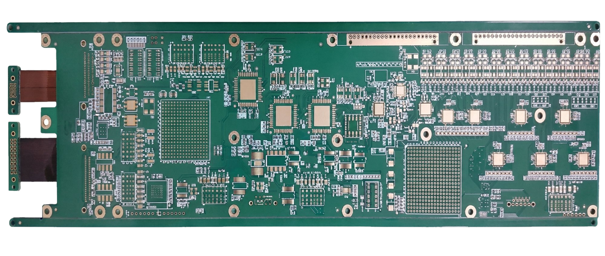
Design Engineering
Rigid-Flex Design Rules & Bend Zone Engineering
Bend Zone Design That Survives
The flex zone is where rigid-flex boards fail. Not the rigid sections, not the vias — the bend zone. Our engineering review catches design rule violations that would cause premature fatigue failure, and our recommendations are based on thousands of rigid-flex builds across consumer, medical, and aerospace applications.
Stiffener Options for Component Support
Stiffeners provide local rigidity in flex areas that need mechanical support — typically under connectors, component pads, or areas that interface with ZIF sockets. We offer three stiffener materials depending on your application:
- FR-4 stiffener (0.2-1.6mm): The most common choice. Inexpensive, easy to bond with pressure-sensitive adhesive or thermally-cured epoxy. Best for general connector support and areas needing pick-and-place flatness.
- Polyimide stiffener (0.05-0.2mm): Thinner than FR-4, used when you need moderate stiffness without adding height. Common in ultra-thin consumer devices where every 0.1mm of Z-height matters.
- Stainless steel stiffener (0.1-0.3mm): Maximum rigidity in minimum thickness. Used under high-insertion-force connectors (USB-C, board-to-board) where the flex substrate alone cannot resist mating force without deflection.
Layer Count in Flex Zones
Minimize copper layers in the flex zone — ideally 1-2 copper layers maximum. Every additional layer increases flex section thickness, which directly increases the minimum bend radius (remember: 6x or 12x the total flex thickness). A 4-layer rigid section can transition to 1-2 layers in the flex by dropping internal layers before the rigid-to-flex boundary.
If you must carry more than 2 layers through a flex zone, the traces should be arranged symmetrically about the neutral bend axis. Asymmetric copper distribution puts one side in tension and the other in compression during bending, accelerating fatigue. Symmetric stackups keep the copper at or near the neutral axis where strain is minimal.
Adhesiveless Construction
Traditional flex uses adhesive (typically acrylic or epoxy) to bond copper to the polyimide base film. Adhesiveless (also called "2-layer flex" or "cast-copper" construction) deposits the copper directly onto the polyimide without an adhesive layer. The benefits for bend reliability are significant:
- Thinner total flex section = tighter achievable bend radius
- No adhesive layer to delaminate under repeated cycling
- Better Z-axis dimensional stability (less CTE mismatch)
- Higher temperature tolerance (acrylic adhesive limits to ~105°C; adhesiveless handles 200°C+)
We recommend adhesiveless construction for all dynamic flex applications and any design requiring bend radius below 3mm. The material cost premium is approximately 15-20% over adhesive-based flex, which is easily justified by the reliability improvement.
Transition Zone Design: Rigid-to-Flex Interface
The rigid-to-flex transition is the second most common failure point (after the bend zone itself). The abrupt change in stiffness creates a stress concentration line where the rigid section ends and the flex begins. Poor transition design concentrates all bending stress at a single line, causing premature copper cracking at that exact point.
Our design rules for reliable transitions:
- Tapered transition: The rigid section tapers from full thickness to flex thickness over 2-3mm rather than dropping off abruptly. This distributes the bending stress over a wider area.
- Anchor pads: Copper anchor pads (non-functional, unconnected) are placed in the transition zone to "pin" the flex layers to the rigid section and prevent peel-back during bending.
- No vias within 1.0mm of transition: Plated vias near the transition create rigid spots that concentrate stress. Keep all vias at least 1.0mm (preferably 1.5mm) from the rigid-to-flex boundary line.
- Coverlay overlap: The polyimide coverlay should extend 1.0-1.5mm into the rigid section (under the solder mask) to provide a smooth mechanical transition rather than a hard edge at the flex boundary.
- Trace routing at transition: Stagger traces so they do not all cross the transition line at the same point. Fan them out to distribute stress across a wider area of the boundary.
We review every rigid-flex design for transition zone compliance before production. If your current layout has vias in the transition zone or an abrupt thickness change, we will flag it with specific relocation recommendations — not just a generic "design error" message.
Minimum Bend Radius
6x flex section thickness for static applications. 12x for dynamic (>500K cycles). A 0.2mm flex section requires minimum 1.2mm static radius, 2.4mm dynamic.
Copper Selection
Rolled annealed (RA) copper for dynamic flex — the elongated grain structure resists fatigue cracking. Electrodeposited (ED) copper is acceptable for static-only flex zones where cost matters more than cycle life.
Grain Direction Alignment
Traces must run perpendicular to the bend axis. Copper grain direction follows the rolling direction — bending along the grain creates intergranular crack propagation. Perpendicular routing forces cracks across grains, requiring far more energy to propagate.
Coverlay vs Flex Solder Mask
Polyimide coverlay for all bend zones — it flexes with the copper without cracking. Flex solder mask (LPI type) is only for non-bend areas where you need SMD pad openings. Never put LPI solder mask across a dynamic bend zone; it will crack within 1,000 cycles.
FAQ
Rigid-Flex Questions
How does cost compare to separate rigid + FPC?
Per-board cost is higher. Total system cost is often lower when you factor in eliminated connectors, reduced assembly labor, smaller enclosures, and improved field reliability. ROI is strongest in volume production or high-reliability applications.
Dynamic vs static — what is the difference?
Static flex bends once during assembly and stays fixed (most common). Dynamic flex bends repeatedly in use — requires thinner PI, perpendicular trace routing, no plating in bend zone, and larger bend radius.
What is the prototype lead time?
11 days for 2-layer. Approximately 1 day per 2 additional layers. Most designs (4-8L) ship in 12-14 days.
What is the minimum bend radius?
The rule of thumb: 6x the flex section thickness for static applications (installed once, never moved again). 12x flex thickness for dynamic applications (repeated bending over the product lifetime). For a typical 0.2mm flex section, that means 1.2mm minimum bend radius for static and 2.4mm for dynamic. These numbers assume single-layer flex with 1/2oz RA copper — add thickness for each additional copper layer and recalculate. We verify bend radius feasibility for every order and will flag designs that violate minimum radius before production.
How many flex cycles can the board survive?
With rolled annealed (RA) copper, proper grain orientation (traces perpendicular to bend axis), and adhesiveless construction: 500,000+ cycles for dynamic applications at the rated bend radius. Some designs exceed 1 million cycles in testing. Static flex — installed once during assembly and never moved again — has effectively infinite life. The critical factors are copper type (RA, not ED), grain direction, layer count in the flex zone, and whether you respect the minimum bend radius. Violate any of these and fatigue life drops dramatically.
Can I put components in the flex zone?
For dynamic flex (repeated bending): not recommended. Component solder joints create stress concentration points at the boundary between the rigid component and the flexing substrate. Every bend cycle fatigues those joints. For static flex (bends once during installation): yes, with a polyimide or FR-4 stiffener bonded to the back side of the flex beneath the components. The stiffener prevents the flex from bending under the component area during assembly and provides mechanical support for soldering. Keep components at least 2.5mm away from any bend transition line.
Considering Rigid-Flex?
Upload your design or contact engineering for a stackup consultation. We'll confirm bend feasibility before you commit.
Resources
Rigid-Flex Engineering Guides
Design rules, material selection, and cost considerations for rigid-flex PCBs.
Flex and Rigid-Flex PCB Design Guidelines
Bend radius rules, conductor routing, stiffener placement, and material selection.
Dynamic Flex PCB Design: Bend Radius, Materials, and Reliability
Design rules for flex sections that bend repeatedly in use.
Flex PCB Coverlay vs Solder Mask Selection
Material selection and bend reliability comparison for flex protection layers.
Rigid vs Flexible PCB: Materials, Applications, and How to Choose
Decision framework for choosing between rigid, flex, and rigid-flex constructions.
PCB Copper Foil: ED vs RA for Flex Applications
Why rolled-annealed copper is critical for dynamic flex reliability.
Castellated Holes in PCBs: Design Rules and Module Applications
Plating requirements for board-to-board connections in modular rigid-flex assemblies.