· Marcus Lin · Engineering · 10 min read
FR-4 vs Rogers PCB
Choosing between FR-4 and Rogers PCB material affects signal integrity, cost, and manufacturing complexity. This comparison covers dielectric properties, loss performance, frequency limits, and the hybrid stackup approach that gives engineers the best of both worlds.
Quick Answer
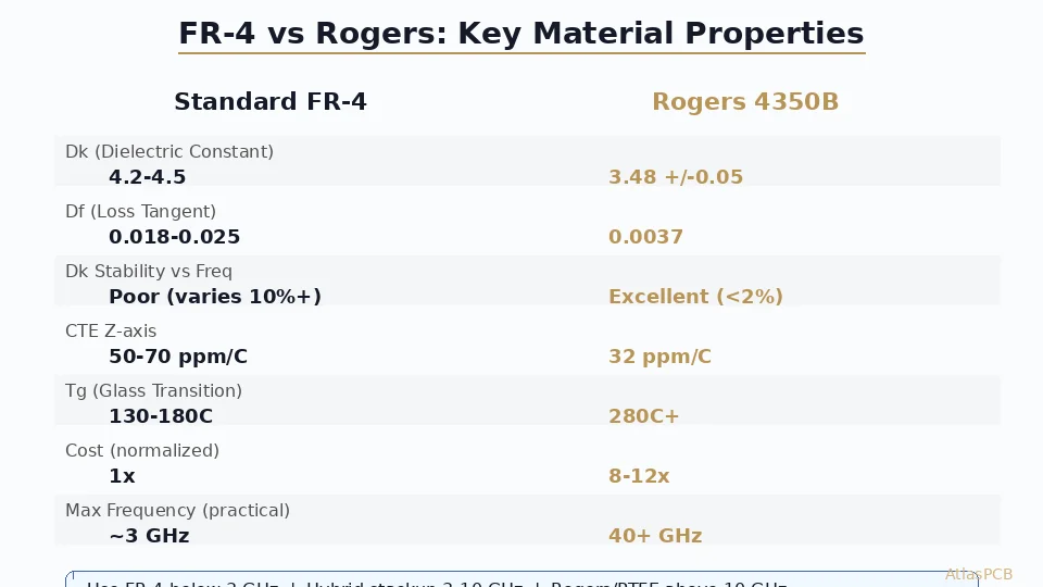
Use FR-4 for digital designs below 3 GHz where 0.018-0.025 Df is acceptable. Switch to Rogers 4350B (Df 0.0037) when your signal path loss budget cannot tolerate FR-4 dielectric loss — typically above 6 GHz, or in any application requiring tight Dk stability for impedance-controlled transmission lines. For mixed RF/digital designs, a hybrid Rogers+FR-4 stackup provides RF-grade performance on critical layers while keeping costs 40-60% below all-Rogers construction.
Quick Decision: FR-4 vs Rogers PCB Material
| Criteria | Standard FR-4 | Rogers RO4350B |
|---|---|---|
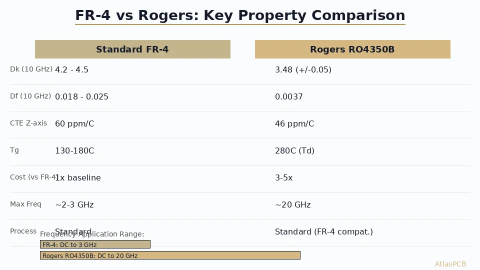
| Dk (10 GHz) | 4.2-4.5 (varies with freq) | 3.48 +/-0.05 (stable) |
| Df (loss tangent) | 0.018-0.025 | 0.0037 |
| Practical frequency limit | ~3-6 GHz | 40+ GHz |
| CTE (Z-axis) | 50-70 ppm/C | 32 ppm/C |
| Material cost | 1x (baseline) | 8-12x |
| Processing compatibility | Standard | FR-4 compatible |
| Lead time impact | None | +3-5 days typical |
| Recommended use | Digital, power, low-freq analog | RF, microwave, mmWave, high-speed serial |
If your highest-frequency signal is below 3 GHz and traces are under 4 inches, FR-4 almost certainly works. If you are designing above 6 GHz, dealing with antenna elements, or need insertion loss below 0.3 dB/inch, Rogers (or similar low-loss laminate) is the engineering-correct choice.
The Real Engineering Tradeoff: Loss Budget vs Cost
The decision between FR-4 and Rogers is fundamentally about signal loss — specifically, whether your link budget can absorb the dielectric loss that FR-4 introduces at your operating frequency. Understanding this quantitatively is what separates a good material selection from a guess.
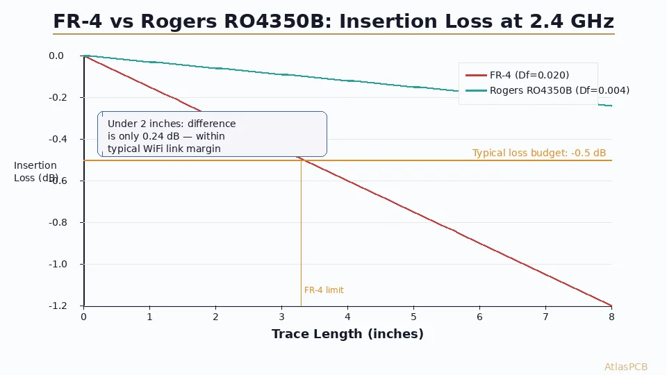
At 1 GHz, FR-4 introduces approximately 0.02-0.04 dB/inch of dielectric loss on a 50-ohm microstrip. That is perfectly acceptable for most digital interfaces — USB, Ethernet, even PCIe Gen 3. At 10 GHz, that same FR-4 trace loses 0.15-0.25 dB/inch from dielectric absorption alone, before accounting for copper roughness loss. A 6-inch trace at 10 GHz on FR-4 therefore loses 1.0-1.5 dB just from the substrate — and if your system has 3 dB of margin total, half your budget is consumed by the board material.
Rogers RO4350B at 10 GHz contributes roughly 0.03 dB/inch of dielectric loss — an 80% reduction compared to standard FR-4. On that same 6-inch trace, you save approximately 0.7-1.2 dB of insertion loss, which translates directly into system margin, reduced amplifier gain requirements, or the ability to use lower-cost connectors and cables elsewhere in the signal chain.
In our fabrication facility, we track insertion loss measurements on impedance-controlled RF boards using vector network analyzers up to 40 GHz. Based on production data across 2,000+ RF panels in the last year, the typical insertion loss we achieve on Rogers 4350B is 0.08 dB/inch at 10 GHz (including copper roughness effects), compared to 0.22 dB/inch on high-quality Shengyi S1000-2M FR-4 at the same frequency.
IMPEDANCE CONTROLLED PCB MANUFACTURER
Rogers and FR-4 Hybrid Stackup Fabrication
We fabricate hybrid Rogers/FR-4 stackups daily. Our process engineers help you optimize layer assignment to minimize RF loss while controlling cost. Impedance tolerance held to +/-5% on all controlled layers.
Get RF PCB Quote ›
Dielectric Constant Stability: The Hidden Advantage of Rogers
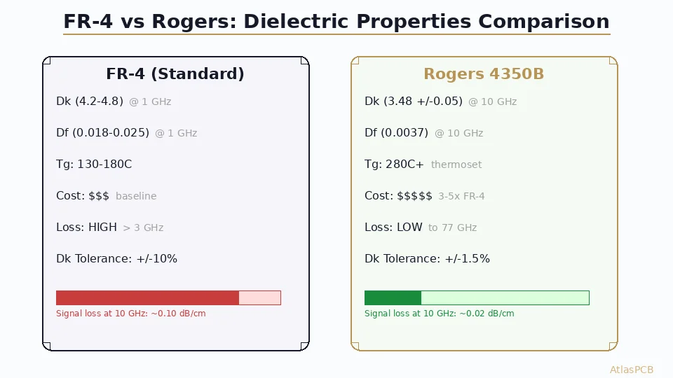
Engineers often focus on loss tangent (Df) when comparing materials, but Dk stability across frequency is equally important for impedance-controlled designs. Standard FR-4 has a specified Dk of 4.2-4.5 — that range itself tells you the problem. The actual Dk varies with frequency, resin content, glass weave style, and even the direction of measurement relative to the glass cloth.
On a typical FR-4 stackup, the effective Dk at 1 GHz might be 4.3, but at 10 GHz it shifts to 4.0-4.1 due to the frequency-dependent behavior of the epoxy resin. For a 50-ohm impedance-controlled trace designed at Dk=4.3, this frequency-dependent Dk shift means your actual impedance rises to approximately 52-53 ohms at 10 GHz — a 4-6% deviation that causes reflections and degrades eye diagrams on high-speed serial links.
Rogers RO4350B specifies Dk of 3.48 +/-0.05 and maintains this value essentially flat from 1 MHz to 40 GHz. Our impedance testing data confirms this: on boards we fabricate with RO4350B, measured impedance variation across frequency is typically within +/-1.5% from DC to 20 GHz. This stability eliminates the need to de-rate your impedance targets or add guardband — what you simulate is what you measure.
Another practical consideration is lot-to-lot Dk consistency. Standard FR-4 from the same manufacturer can vary +/-0.15 in Dk between different production lots. Rogers guarantees +/-0.05 lot-to-lot, and from our incoming material inspection data, we typically see +/-0.02 within a single material shipment. For antenna designs where Dk directly sets resonant frequency, this consistency is not optional — it is essential.
The Hybrid Stackup Solution: Best of Both Worlds
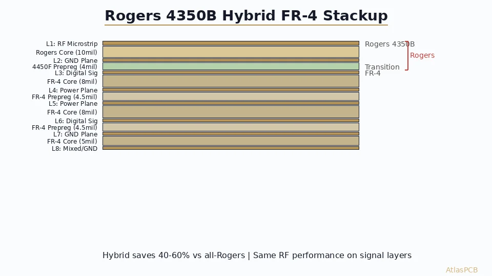
For most real-world RF/mixed-signal designs, the answer is not “FR-4 or Rogers” but rather “Rogers where you need it, FR-4 everywhere else.” A hybrid stackup places Rogers material on the layers carrying RF signals while using FR-4 for digital routing, power distribution, and ground planes that do not see high-frequency energy.
A typical 8-layer hybrid stackup for a 5G small cell or Wi-Fi 7 access point might look like this:
| Layer | Material | Function | Dk |
|---|---|---|---|
| L1 | RO4350B (10 mil) | RF traces, antenna feed | 3.48 |
| PP | Rogers 4450F (4 mil) | RF-to-FR4 bond | 3.54 |
| L2 | FR-4 copper | Ground plane | - |
| Core | FR-4 (8 mil) | FR-4 core | 4.2 |
| L3 | FR-4 copper | Digital high-speed | - |
| PP | Standard FR-4 PP | Standard bond | 4.2 |
| L4-L5 | FR-4 | Power/ground pair | 4.2 |
| PP | Standard FR-4 PP | Standard bond | 4.2 |
| L6 | FR-4 copper | Digital routing | - |
| Core | FR-4 (8 mil) | FR-4 core | 4.2 |
| L7 | FR-4 copper | Ground plane | - |
| PP | Rogers 4450F (4 mil) | RF-to-FR4 bond | 3.54 |
| L8 | RO4350B (10 mil) | RF traces (bottom) | 3.48 |
This architecture provides full RF performance on L1 and L8 — suitable for filters, couplers, power amplifiers, and feed networks operating up to 28 GHz — while the inner FR-4 layers handle digital ICs, power regulation, and control logic at standard FR-4 cost.
The manufacturing challenge is at the Rogers-to-FR-4 interface. The CTE mismatch (Rogers X/Y: 10-12 ppm/C, FR-4 X/Y: 14-16 ppm/C) creates stress during thermal cycling that can cause delamination if the bonding prepreg is not compatible. In our facility, we exclusively use Rogers 4450F prepreg for this interface — it has intermediate CTE properties that bridge the mismatch and provides reliable adhesion to both material families through standard lamination cycles at 375F/200 psi.
CHINA RF PCB MANUFACTURER
Hybrid Rogers + FR-4 Stackup Expertise
We fabricate 200+ hybrid stackup designs monthly. Send your RF stackup requirements and we will propose an optimized layer assignment balancing performance and cost.
Upload Stackup for Review ›When FR-4 Is Actually the Right Choice
Not every high-frequency design needs Rogers. Engineers sometimes over-specify material out of caution, adding significant cost without proportional benefit. Here are cases where FR-4 remains perfectly adequate:
Digital high-speed serial links (PCIe Gen 4/5, USB4, 100G Ethernet) operate at frequencies where loss matters, but the signal encoding and equalization at the receiver compensate for moderate channel loss. A PCIe Gen 5 link at 32 GT/s (16 GHz fundamental) can tolerate up to 25 dB of channel insertion loss — which FR-4 can achieve on traces under 8 inches if you select a mid-loss FR-4 (Shengyi S1000-2M, Isola 370HR) with Df around 0.012 and use smooth copper foil (RTF or VLP profiles).
For prototype and development boards where the goal is functional verification rather than production-optimized performance, FR-4 simplifies manufacturing, reduces lead time, and costs 3-4x less. You can always validate the design concept on FR-4 and switch to Rogers for production if measurements confirm that material loss is the limiting factor.
Power distribution networks, ground planes, and low-frequency analog circuits (below 1 GHz) have no engineering justification for Rogers material. Even within a hybrid stackup, these layers should remain FR-4 — the dielectric loss on a power plane is irrelevant, and the additional cost of Rogers in these positions provides zero benefit.
Failure Modes: What Goes Wrong with the Wrong Material Choice
We see two categories of material-related failures in our DFM review process. The first is using FR-4 where it cannot perform: an engineer designs a 10 GHz amplifier on standard FR-4 and finds 3-4 dB more loss than simulation predicted, because the simulator used “nominal” FR-4 Dk/Df values rather than worst-case, and the copper roughness contribution was underestimated. By the time they realize the issue, they have 50 prototypes that do not meet spec.
The second is the opposite mistake: specifying Rogers throughout an entire stackup when only two layers carry RF signals. We recently reviewed a 12-layer design where the engineer specified RO4003C on all layers — at a material cost of approximately $850 per panel. Our suggestion to move to a hybrid stackup (RO4003C on L1/L2, FR-4 on L3-L12) reduced material cost to $280 per panel with identical RF performance on the critical signal layers.
The correct approach is to analyze your signal chain, identify which nets actually carry frequencies above your FR-4 threshold, and assign Rogers material only to the layer pairs those nets route on. Every other layer should be FR-4 or mid-loss laminate (Isola 370HR for the 4-10 GHz transition zone).
RF PCB DESIGN AND MANUFACTURING
Not Sure Which Material You Need?
Our RF engineers review stackup proposals and recommend optimal material assignment. Send your design frequency, loss budget, and layer count for a recommendation.
Material Selection Decision Framework
The decision should follow this logic:
Step 1: Identify your highest operating frequency. Not the data rate — the highest significant spectral content. For NRZ signaling, this is approximately 0.7x the data rate. For PAM4, it is approximately 0.35x the baud rate.
Step 2: Determine your loss budget. How much total insertion loss can your receiver tolerate? Subtract connector losses, via transition losses, and copper roughness loss. The remainder is your dielectric loss budget.
Step 3: Calculate required Df. Dielectric loss (dB/inch) is approximately: 2.3 x f(GHz) x Df x sqrt(Dk). If your Df budget requires a value below 0.010, you need a low-loss or ultra-low-loss laminate. If below 0.005, Rogers or PTFE is mandatory.
Step 4: Choose your material tier:
- Df > 0.015: Standard FR-4 (cost baseline)
- Df 0.008-0.015: Mid-loss FR-4 (Isola 370HR, Shengyi S1000-2M), +20-30% cost
- Df 0.004-0.008: Low-loss (Megtron 4, Isola I-Speed), +50-100% cost
- Df < 0.004: Rogers RO4350B, RO4003C, or PTFE, +300-800% cost (material only)
Step 5: Apply hybrid stackup. Once you know which signals need low-loss material, route them on a dedicated layer pair and keep everything else on FR-4.
ATLASPCB
Ready to Specify Your RF Stackup?
Upload your Gerber files or stackup requirements. Our engineers will recommend the optimal material combination for your frequency, budget, and volume — with a quote within 24 hours.
Get Instant Quote ›
Reviewed by AtlasPCB Engineering Team — 15+ years in advanced PCB fabrication for RF, HDI, and rigid-flex applications.
Related Reading:
- Hybrid PCB Stackup Design: Combining Rogers and FR4 for Cost-Effective RF Performance
- What Is Rogers PCB Material? Properties, Types & Applications
- High-Frequency PCB Design Best Practices: RF/Microwave Layout, Ground Planes, Via Fencing
- Signal Integrity in PCB Design: Impedance Control, Crosstalk, Via Stubs, and Return Paths
About AtlasPCB — We specialize in complex PCB manufacturing for HDI, RF, and high-reliability applications. Explore our RF and high-frequency PCB services, Rogers RO4350B PCB manufacturing, or get an impedance-controlled PCB manufacturing . Every order includes free engineering review. Get your quote.
Reviewed by AtlasPCB Engineering Team — IPC-certified manufacturing specialists with 15+ years of production experience in HDI, RF, and high-reliability PCB fabrication. Content based on factory floor data and real customer design reviews.
Frequently Asked Questions
At what frequency should I switch from FR-4 to Rogers?
How much more does Rogers PCB cost compared to FR-4?
Can I mix Rogers and FR-4 in the same PCB stackup?
Is Rogers 4350B compatible with standard PCB manufacturing processes?
What Rogers material should I use for 5G mmWave above 24 GHz?
- FR-4 vs Rogers PCB
- Rogers 4350B stackup
- RF PCB
- PCB material selection
- impedance controlled PCB