· Marcus Lin · Engineering · 7 min read
Taconic TLY-5 PCB
Technical reference for Taconic TLY-5 PTFE-based RF laminate. Covers dielectric properties, processing requirements, stackup design, and practical comparison with Rogers alternatives for high-frequency PCB applications.
Quick Answer
Taconic TLY-5 is a woven fiberglass-reinforced PTFE laminate with Dk 2.20 ±0.02 at 10GHz and Df 0.0009 at 10GHz. It provides ultra-low dielectric loss comparable to Rogers RT/duroid 5880 but with better dimensional stability due to its woven glass reinforcement. TLY-5 is specified for applications above 10GHz where loss budgets are tight: satellite communication, radar systems, phased array antennas, and millimeter-wave front-ends.
Taconic TLY-5 occupies a specific niche in the RF laminate landscape: PTFE-level electrical performance with glass-reinforced mechanical stability. When your design operates above 10GHz and your loss budget demands better than Rogers 4003C or 4350B can deliver, TLY-5 is one of the materials on the short list.
This guide covers what you need to know to specify and manufacture with TLY-5 — properties, processing requirements, stackup considerations, and practical trade-offs against alternative materials.
Material Overview
Taconic TLY-5 is a woven E-glass reinforced PTFE (polytetrafluoroethylene) composite laminate. The “TLY” family from Taconic uses different filler loadings to achieve different Dk values; TLY-5 targets Dk 2.20, making it a direct alternative to Rogers RT/duroid 5880.
Electrical Properties
| Property | Value | Test Condition |
|---|---|---|
| Dielectric constant (Dk) | 2.20 ±0.02 | 10GHz, IPC-TM-650 2.5.5.5 |
| Dissipation factor (Df) | 0.0009 | 10GHz |
| Dk variation with frequency | ±1% | 1GHz to 40GHz |
| Dk variation with temperature | ±0.3% | -55°C to +125°C |
| Volume resistivity | >10⁷ MΩ·cm | ASTM D257 |
| Surface resistivity | >10⁷ MΩ | ASTM D257 |
| Dielectric breakdown | >40 kV/mm | IPC-TM-650 2.5.6 |
Mechanical Properties
| Property | Value | Test Condition |
|---|---|---|
| Tg | — (PTFE: no distinct Tg) | — |
| Td (decomposition) | >500°C | TGA |
| CTE x-axis | 10 ppm/°C | TMA |
| CTE y-axis | 12 ppm/°C | TMA |
| CTE z-axis | 150 ppm/°C | TMA, below 200°C |
| Flexural strength | 22,000 PSI | ASTM D790 |
| Peel strength | 6.0 lb/in | 1oz ED copper, after solder float |
| Moisture absorption | 0.02% | IPC-TM-650 2.6.2.1, 48hr |
| Density | 2.20 g/cm³ | ASTM D792 |
| Flammability | V-0 | UL 94 |
Available Configurations
| Dielectric Thickness (mil) | Dielectric Thickness (mm) | Available Copper |
|---|---|---|
| 5 | 0.127 | ½oz, 1oz |
| 10 | 0.254 | ½oz, 1oz, 2oz |
| 15 | 0.381 | ½oz, 1oz, 2oz |
| 20 | 0.508 | ½oz, 1oz, 2oz |
| 30 | 0.762 | ½oz, 1oz, 2oz |
| 40 | 1.016 | ½oz, 1oz |
| 60 | 1.524 | ½oz, 1oz |
| 62 | 1.575 | ½oz, 1oz |
Why TLY-5: The Low-Loss Advantage
Insertion Loss Comparison
The primary reason to specify TLY-5 is insertion loss. At millimeter-wave frequencies, the difference between Df 0.0009 (TLY-5) and Df 0.0027 (Rogers 4003C) is not academic — it is the difference between a working radar module and a failed link budget.
For a 50Ω microstrip, 50mm long:
| Frequency | TLY-5 Loss | 4003C Loss | FR4 Loss | TLY-5 Advantage |
|---|---|---|---|---|
| 5 GHz | 0.12 dB | 0.28 dB | 1.8 dB | 2.3x lower than 4003C |
| 10 GHz | 0.22 dB | 0.52 dB | 3.5 dB | 2.4x lower |
| 24 GHz | 0.48 dB | 1.15 dB | — | 2.4x lower |
| 40 GHz | 0.75 dB | 1.80 dB | — | 2.4x lower |
| 77 GHz | 1.35 dB | 3.20 dB | — | 2.4x lower |
At 77GHz over 50mm, TLY-5 saves 1.85 dB compared to 4003C. In a radar receiver with an 8-element patch array and corporate feed network, that difference can mean 3-5 dB of total system improvement.
Dimensional Stability: TLY-5 vs Unreinforced PTFE
The woven glass in TLY-5 provides mechanical stability that unreinforced PTFE laminates lack:
| Property | TLY-5 (glass-reinforced) | RT/duroid 5880 (microfiber glass) | Unreinforced PTFE |
|---|---|---|---|
| CTE x-axis | 10 ppm/°C | 31 ppm/°C | 70-100 ppm/°C |
| CTE y-axis | 12 ppm/°C | 48 ppm/°C | 70-100 ppm/°C |
| Dimensional stability during processing | Good | Moderate | Poor |
| Registration accuracy | ±2 mil | ±3-4 mil | ±5-8 mil |
| Drillability | Good with modified params | Good with modified params | Difficult |
For multilayer PTFE designs with tight layer-to-layer registration (phased array antenna boards, for example), TLY-5’s glass reinforcement provides a meaningful manufacturing advantage.
Processing TLY-5: What Your Manufacturer Needs to Know
PTFE materials require specialized processing. If your manufacturer routinely builds on RT/duroid 5880, they can handle TLY-5. If they have only FR4 experience, TLY-5 will require process development.
Surface Preparation for Copper Adhesion
PTFE surfaces are chemically inert — standard electroless copper chemistry will not adhere. Two preparation methods are used:
Sodium etch (chemical):
- Immerse exposed PTFE surfaces in sodium/naphthalene solution
- Creates a chemically modified surface layer that accepts electroless copper
- Proven process, widely used
- Environmental concerns with sodium/naphthalene waste
Plasma treatment (dry process):
- Expose PTFE surfaces to CF₄/O₂ or Ar/O₂ plasma
- Roughens and chemically activates the surface
- Cleaner process, no wet chemistry waste
- Requires plasma chamber equipment
Both methods achieve adequate peel strength (>4 lb/in) for reliable plated through-holes.
Drilling
| Parameter | TLY-5 Recommendation | FR4 Standard |
|---|---|---|
| Drill bit | Carbide, freshly sharpened | Standard carbide |
| Chip load | 0.5-1.0 mil/rev | 1.0-2.0 mil/rev |
| Surface speed | 250-350 SFM | 350-500 SFM |
| Stack height | 1-2 panels | 2-3 panels |
| Entry material | Aluminum sheet | Phenolic or aluminum |
| Backup material | Phenolic | Phenolic or wood composite |
| Hit count | 500-750 hits | 1000-1500 hits |
Key difference: Lower feed rate and surface speed prevent PTFE smearing, which creates resin deposits on hole walls that block copper plating.
Lamination (Multilayer)
For multilayer TLY-5 constructions, Taconic provides TacBond bondply (Dk 2.35) for inter-layer bonding:
| Parameter | Recommendation |
|---|---|
| Bondply material | TacBond HT 1.5 (Dk 2.35) |
| Lamination temperature | 425°F (218°C) |
| Pressure | 200-400 PSI |
| Time at temperature | 60-120 minutes |
| Ramp rate | 5-8°F/min |
| Cool-down | Under pressure to <200°F |
Engineer’s Note: PTFE multilayer lamination requires careful thermal profiling. Unlike FR4 where the resin flows and self-levels, PTFE bondply has a narrower processing window. Request lamination qualification data from your manufacturer before committing to production.

Stackup Design with TLY-5
All-PTFE Stackup (2-6 Layers)
For pure RF boards where all signal layers require ultra-low loss:
Layer 1: RF signal — TLY-5, 10mil
         TacBond HT bondply
Layer 2: Ground plane — 1oz copper
         TLY-5 core, 20mil
Layer 3: RF signal / DC routing
         TacBond HT bondply
Layer 4: Ground plane — 1oz copper
         TLY-5, 10mil
Layer 5: RF signal — microstrip
Hybrid PTFE/FR4 Stackup
For mixed RF + digital designs, keep PTFE for RF layers and use FR4 for digital/power:
Layer 1: RF signal — TLY-5, 10mil (microstrip)
         TacBond HT bondply
Layer 2: Ground plane — 1oz copper
         FR4 prepreg (standard)
Layer 3: Digital signal — FR4
         FR4 prepreg
Layer 4: Power plane — 1oz copper
         FR4 prepreg
Layer 5: Ground plane — 1oz copper
         TacBond HT bondply
Layer 6: RF signal — TLY-5, 10mil (microstrip)
Caution: The PTFE/FR4 interface requires careful CTE management. TLY-5’s z-axis CTE (150 ppm/°C) is significantly higher than FR4 (50-70 ppm/°C), creating stress at the interface during thermal cycling. Minimize via count through the PTFE/FR4 boundary and use thermal relief on ground vias.
Impedance Calculations
For TLY-5 with Dk 2.20, a 50Ω microstrip requires a wider trace than on FR4 or Rogers 4003C:
| Dielectric | Dk | 50Ω Microstrip Width (10mil substrate, 1oz Cu) |
|---|---|---|
| TLY-5 | 2.20 | 28.5 mil (0.72mm) |
| Rogers 4003C | 3.38 | 22.0 mil (0.56mm) |
| Rogers 4350B | 3.48 | 21.5 mil (0.55mm) |
| FR4 | 4.30 | 18.5 mil (0.47mm) |
The wider trace on TLY-5 reduces conductor loss (lower resistance per unit length), partially offsetting the wider board area required. This is actually a performance benefit at high frequencies where conductor loss dominates.
Application Guide
Primary Applications
| Application | Frequency | Why TLY-5 |
|---|---|---|
| Automotive radar | 77 GHz | Ultra-low loss at mmWave, temperature stable |
| Phased array antennas | 10-40 GHz | Dimensional stability for element spacing accuracy |
| Satellite transponders | 12-18 GHz (Ku) | Low loss for receiver noise figure |
| Weather radar | 5.6 GHz (C-band), 9.4 GHz (X-band) | Long trace runs require low Df |
| Electronic warfare | Wideband (2-18 GHz) | Low loss across wide bandwidth |
| 5G mmWave backhaul | 28/39 GHz | Low insertion loss for link budget |
| Test fixtures | DC-67 GHz | Predictable Dk for calibration reference |
When TLY-5 Is Not Needed
- Below 5GHz: Rogers 4003C or 4350B provides adequate loss at significantly lower cost and easier processing
- Consumer products: Cost-sensitive designs should evaluate low-loss FR4 (Megtron 6, Dk 3.71, Df 0.004) before committing to PTFE
- Flex circuits: TLY-5 is rigid; consider liquid crystal polymer (LCP) for flexible RF
- High layer count (>8): PTFE multilayer registration challenges increase with layer count; consider hybrid approaches
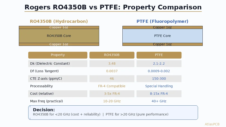
TLY-5 vs Alternative PTFE Materials
| Property | TLY-5 | RT/duroid 5880 | RT/duroid 6002 | IT-958 |
|---|---|---|---|---|
| Dk @ 10GHz | 2.20 | 2.20 | 2.94 | 2.20 |
| Df @ 10GHz | 0.0009 | 0.0009 | 0.0012 | 0.0010 |
| Reinforcement | Woven E-glass | Microfiber glass | Random microfiber | Woven E-glass |
| CTE x/y (ppm/°C) | 10/12 | 31/48 | 16/16 | 8/10 |
| CTE z (ppm/°C) | 150 | 237 | 24 | 130 |
| Dimensional stability | Good | Moderate | Good | Excellent |
| Relative cost | 1x (PTFE baseline) | 1.0-1.2x | 1.5-2.0x | 1.2-1.5x |
| Availability | Good | Excellent | Good | Moderate |
Decision framework:
- Best availability + spec compliance: RT/duroid 5880
- Best dimensional stability at low cost: TLY-5
- Lowest z-axis CTE: RT/duroid 6002
- Best overall mechanical properties: Isola IT-958
Design Checklist for TLY-5
- Confirm application frequency justifies PTFE cost (>5GHz typically)
- Verify manufacturer has PTFE processing capability (sodium etch or plasma)
- Specify Dk 2.20 ±0.02 in stackup notes
- Use TacBond HT bondply for multilayer construction
- Account for wider trace widths in routing (Dk 2.20 = wider 50Ω trace)
- Minimize via count through PTFE/FR4 interfaces in hybrid stackups
- Specify modified drill parameters in fab notes
- Request lamination qualification coupon for multilayer builds
- Add TDR coupon to panel for impedance verification
- Verify z-axis CTE compatibility in thermal cycling profile
How Atlas PCB Handles TLY-5
Atlas PCB’s partner factories maintain full PTFE processing capabilities including sodium etch surface preparation, modified drilling protocols, and TacBond lamination qualification. We process TLY-5 alongside other PTFE materials (RT/duroid 5880, 6002, 6035HTC) on dedicated PTFE production lines.
Atlas PCB fabricates Taconic TLY-5 boards in 2-8 layer configurations with ±5% impedance control, hybrid PTFE/FR4 stackups, and full PTFE processing capability including plasma desmear and modified drilling. Every TLY-5 order includes our 12-hour human engineering review, where we verify stackup feasibility, material interface compatibility, and drilling parameters before production starts.
Summary
- Taconic TLY-5 delivers Dk 2.20 / Df 0.0009 — ultra-low loss with woven glass stability
- Better dimensional stability than RT/duroid 5880 thanks to woven glass reinforcement
- PTFE processing required — not FR4-compatible; manufacturer must have PTFE capability
- Ideal for 10GHz+ applications where every 0.1 dB of insertion loss matters
- Hybrid stackups with FR4 reduce cost while maintaining RF performance on critical layers
Building a millimeter-wave or radar PCB? Upload your Gerbers for a free engineering review — we will verify your PTFE stackup and drilling specifications before production.
Related guides: [Rogers 4350B vs FR4]/blog/rogers-4350b-vs-fr4/) | [RF PCB Design Guidelines]/blog/rf-pcb-design-guidelines/) | [RF PCB Materials Comparison]/blog/rf-pcb-materials-comparison/) | [HDI PCB Design Guide]/blog/hdi-pcb-design-guide/)
Further Reading
[Rogers 4003C Material Properties: Dk, Df, and Design Considerations]/blog/rogers-4003c-properties/)
[Multilayer PCB Stackup Design Guide: 8 to 30+ Layers Step by Step]/blog/multilayer-pcb-stackup-design-guide/)
[PCB Manufacturer with Engineering Review: Why Human DFM Audit Matters]/blog/pcb-manufacturer-engineering-review/)
[PCB Grounding Techniques: Star, Split, and Solid Ground Plane Strategies]/blog/pcb-grounding-techniques/)
[PCB DFM Checklist: 50 Points to Review Before Sending Gerbers]/blog/pcb-dfm-checklist/)
About AtlasPCB — We specialize in complex PCB manufacturing for HDI, RF, and high-reliability applications. Explore our RF and high-frequency PCB services . Every order includes free engineering review. Get your quote.
Reviewed by AtlasPCB Engineering Team — IPC-certified manufacturing specialists with 15+ years of production experience in HDI, RF, and high-reliability PCB fabrication. Content based on factory floor data and real customer design reviews.
Frequently Asked Questions
How does Taconic TLY-5 compare to Rogers RT/duroid 5880?
What special processing does TLY-5 require?
What is the maximum frequency for TLY-5?
- Taconic TLY-5
- PTFE
- RF PCB
- high frequency
- pcb material
- microwave