· David Okafor · Engineering · 8 min read
Rigid-Flex PCB Manufacturer
Selecting a rigid-flex PCB manufacturer requires verifying specific capabilities most standard shops lack. This guide covers the qualification criteria, cost drivers, design-for-manufacturing rules, and what separates a capable rigid-flex house from a standard PCB shop claiming flex capability.
Quick Answer
A qualified rigid-flex PCB manufacturer must demonstrate three capabilities most standard shops lack: polyimide processing with adhesiveless flex materials (for dynamic flex applications), sequential lamination integrating flex layers with rigid sections, and bend radius verification testing per IPC-2223. Expect 3-5x cost premium over equivalent rigid boards due to polyimide material cost, additional lamination cycles, and manual processing steps. The critical selection factor is their rigid-to-flex transition design — poor transition manufacturing is the primary failure mode in rigid-flex boards.
The 30-Second Assessment
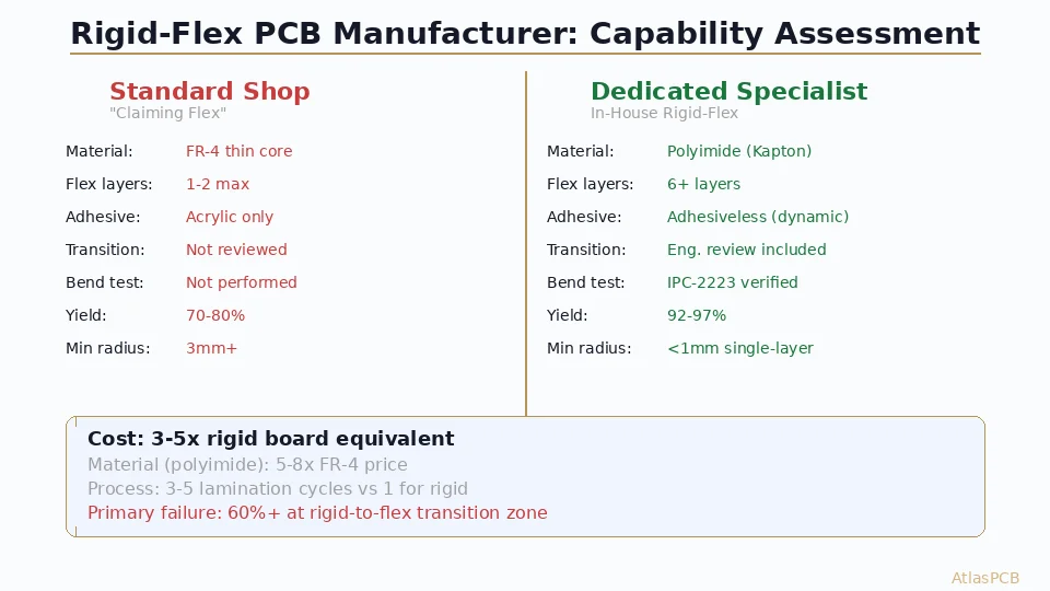
| Factor | Standard PCB Shop “Doing Flex” | Dedicated Rigid-Flex Manufacturer |
|---|---|---|
| Flex material | FR-4 thin core (not true flex) | Polyimide (Kapton, Dupont AP) |
| Max flex layers | 1-2 | 6+ |
| Adhesive system | Acrylic (acceptable for static) | Adhesiveless for dynamic flex |
| Transition design | Customer’s problem | Manufacturer reviews and advises |
| Bend testing | Not performed | IPC-2223 verification standard |
| Min bend radius capability | 3mm+ | <1mm for single-layer |
| Laser drill on flex | Standard FR-4 parameters | Polyimide-specific recipes |
| Typical flex yield | 70-80% | 92-97% |
The core distinction: a standard shop treats rigid-flex as “a rigid board with a thin section” while a dedicated manufacturer engineers the flex portion as a dynamic mechanical interconnect that happens to carry signals.
Why Rigid-Flex Manufacturing Is Fundamentally Different
Rigid-flex fabrication is not simply “making a board thinner in some areas.” The manufacturing process requires a completely different approach to material handling, lamination, and quality control that standard rigid board production lines are not designed to perform.
Polyimide base materials (Dupont Kapton, Panasonic Felios) behave nothing like FR-4 in processing. They absorb moisture readily (requiring baking before lamination), have different CTE profiles (20-25 ppm/C vs 14-16 for FR-4), cannot tolerate the same mechanical handling forces, and require adhesiveless bonding systems for dynamic flex reliability. Every step from material receiving through final electrical test must accommodate these differences.
The sequential lamination process for rigid-flex typically involves 3-5 separate press cycles: flex layers are first imaged and etched, then coverlay is applied, then flex subassemblies are aligned with rigid sections using precision fixtures, and finally the full stackup is laminated. Each cycle introduces registration error that accumulates — maintaining ±50μm layer-to-layer alignment across 3+ press cycles requires fixturing and control that standard shops do not possess.
In our facility, rigid-flex jobs run on a dedicated production line with specialized handling equipment. Flex layers are processed in cleanroom conditions (Class 10,000) because particulate contamination between flex layers causes delamination under bending stress. This is not a concern for rigid boards where layers are permanently compressed together.
RIGID-FLEX SPECIALIST
Rigid-Flex from 4 to 22 Layers — In-House Production
We manufacture rigid-flex in-house with polyimide-specific processing, adhesiveless construction for dynamic flex, and IPC-2223 bend radius verification on every order.

Cost Breakdown: Where the Money Goes
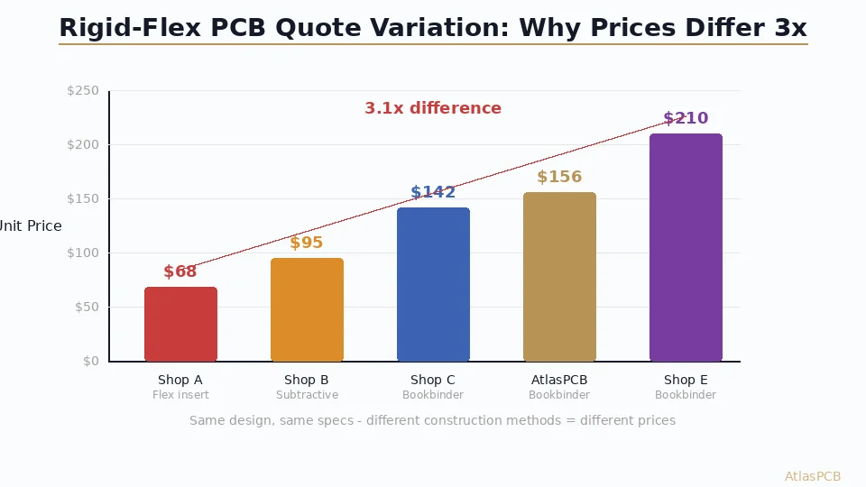
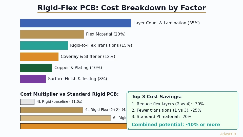
Rigid-flex PCBs cost 3-5x more than equivalent rigid boards. Understanding the cost drivers helps you optimize your design for manufacturability without compromising the flex functionality you need.
Material Cost (35-45% of total)
| Material | Cost per sqft | Application |
|---|---|---|
| Standard FR-4 core | $8-12 | Rigid sections |
| Polyimide film (Kapton) | $40-70 | Flex base material |
| Adhesiveless polyimide | $60-100 | Dynamic flex (required for >10K cycles) |
| Coverlay (polyimide + adhesive) | $25-45 | Flex layer protection |
| FR-4 prepreg (bonding) | $3-5 | Rigid section lamination |
| Stiffener material | $5-15 | Component mounting areas |
Polyimide alone typically costs 5-8x more than FR-4. For a board with 40% flex area, material cost is roughly 3x a pure-rigid equivalent.
Process Cost (40-50% of total)
The multiple lamination cycles, manual handling, and lower yield rates drive process costs significantly above rigid board production:
- Lamination cycles: Each additional press cycle adds 15-25% to process cost. A typical rigid-flex requires 3 cycles vs. 1 for standard multilayer.
- Flex handling: Manual alignment of flex layers in fixtures adds 30-60 minutes per panel vs. automated rigid layer registration.
- Coverlay application: Semi-manual process requiring precision alignment over flex circuit patterns.
- Lower panel utilization: Rigid-flex panels typically achieve 60-75% utilization vs. 85-95% for rigid boards due to flex routing constraints.
- Extended testing: Flex continuity testing, bend verification, and visual inspection of transition zones.
Volume Pricing (examples for 6-layer rigid-flex, 100x80mm)
| Quantity | Per-board cost | Notes |
|---|---|---|
| 5 pieces | $350-550 | Prototype — full NRE amortized |
| 25 pieces | $180-280 | Small batch — NRE spread |
| 100 pieces | $90-150 | Panel optimization engaged |
| 500 pieces | $55-85 | Production efficiency |
| 2000+ pieces | $35-60 | Full volume pricing |
The per-unit cost drops significantly at volume because NRE (tooling, fixtures, process qualification) is amortized. The crossover where rigid-flex becomes cost-competitive with FPC + connector assemblies typically occurs around 500-1000 pieces when connector costs, assembly labor, and reliability requirements are factored in.
COST OPTIMIZATION
Reduce Rigid-Flex Cost Without Compromising Reliability
Upload your design — our engineers identify cost optimization opportunities: stiffener placement, layer count reduction, panel utilization improvement, and material selection guidance.
Get DFM-Optimized Quote ›Critical DFM Rules for Rigid-Flex
The Transition Zone
The rigid-to-flex transition is where 60%+ of rigid-flex failures originate. Manufacturing best practices for this area:
The coverlay must terminate at least 1mm into the rigid section to prevent peeling under mechanical stress. Copper traces crossing the transition must be routed perpendicular to the flex boundary — traces at angles create stress concentrations that crack during bending. Do not place vias within 0.5mm of the transition boundary on either side.
Our DFM review specifically evaluates transition zone design because it is the highest-risk area and the most commonly overlooked by designers working on their first rigid-flex project. We see transition-related design issues in approximately 35% of new rigid-flex designs submitted for quotation.
Flex Zone Design Rules
- Route traces perpendicular to bend axis whenever possible
- Stagger traces on multi-layer flex (do not stack conductors directly above each other)
- Use hatched ground planes in flex zones instead of solid copper fills (reduces stiffness by 40-60%)
- Maintain minimum 2x pad diameter copper-free zone around flex-zone component pads
- Place all components on rigid sections — never mount SMT parts in the flex zone unless using stiffener backup
Stiffener Design
Stiffeners provide mechanical support for components mounted near flex zones and define the flex-to-rigid boundary. Design considerations:
- FR-4 stiffeners (0.3-1.6mm) for standard rigidity
- Stainless steel stiffeners (0.1-0.2mm) when height is constrained
- Polyimide stiffeners (0.05-0.2mm) for partial flexibility
- Stiffener edges should be 0.5-1.0mm from the intended flex boundary to create a graduated transition
DESIGN SUPPORT
First Rigid-Flex Project? We Help You Get It Right
Our DFM team reviews transition zones, bend radius compliance, and stiffener placement — catching the issues that cause 60% of rigid-flex failures before fabrication.
Submit Design for Review ›Applications Driving Rigid-Flex Demand
Aerospace and Defense
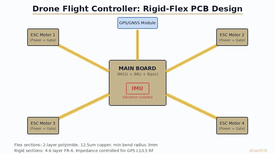
Avionics systems demand rigid-flex for its weight savings (eliminating connectors and cables) and vibration resistance. A typical UAV flight controller replaces 6-8 board-to-board connectors with a single rigid-flex assembly, reducing weight by 15-25g and eliminating connector-related vibration failures entirely. These applications typically require IPC-6013 Class 3 qualification with thermal cycling from -55C to +125C.
Medical Devices
Implantable and wearable medical devices use rigid-flex to achieve form factors impossible with rigid boards and cables. Hearing aids, cardiac monitors, and endoscopic cameras all rely on ultra-thin flex sections (2-3 layers, <0.2mm total) connecting rigid circuit islands. The biocompatibility requirements add another layer of material qualification that most PCB manufacturers cannot support.
Consumer Electronics
Smartphones, smartwatches, and foldable displays use rigid-flex extensively. The smartphone camera module alone typically contains a 4-6 layer rigid-flex connecting the CMOS sensor to the application processor. These applications prioritize ultra-high-volume manufacturing efficiency — a different optimization than the high-reliability aerospace/medical segment.
Manufacturer Evaluation: The Right Questions
When evaluating a rigid-flex PCB manufacturer, ask:
- How many flex layers can you process? (Capability varies from 1-2 at basic shops to 6+ at specialists)
- Do you process adhesiveless polyimide? (Required for dynamic flex applications)
- What is your rigid-flex yield rate? (Below 90% indicates process immaturity)
- Can you provide bend test data per IPC-2223? (Standard qualification evidence)
- Do you manufacture flex in-house or outsource? (Outsourced flex adds cost, time, and coordination risk)
- What is your registration tolerance across lamination cycles? (Should be ±50μm or better)
- Can you show photos/cross-sections of similar builds? (Experience evidence)
ATLASPCB
Rigid-Flex PCB Manufacturing — From Prototype to Production
4-22 layer rigid-flex with adhesiveless polyimide, in-house flex processing, and IPC-6013 Class 3 capability. Upload your design for DFM review and pricing.
Get Rigid-Flex Quote ›
Reviewed by AtlasPCB Engineering Team — 15+ years in advanced PCB fabrication for RF, HDI, and rigid-flex applications.
Related Reading:
About AtlasPCB — We specialize in complex PCB manufacturing for HDI, RF, and high-reliability applications. Explore our HDI PCB manufacturing capabilities, rigid-flex PCB manufacturing, or get an instant online PCB quote . Every order includes free engineering review. Get your quote.
Reviewed by AtlasPCB Engineering Team — IPC-certified manufacturing specialists with 15+ years of production experience in HDI, RF, and high-reliability PCB fabrication. Content based on factory floor data and real customer design reviews.
Frequently Asked Questions
How much does a rigid-flex PCB cost compared to a rigid board?
What is the minimum bend radius for rigid-flex PCBs?
Can any PCB manufacturer do rigid-flex?
What causes rigid-flex PCB failures?
Should I choose rigid-flex or FPC with board-to-board connectors?
- rigid-flex PCB manufacturer
- rigid-flex PCB
- PCB manufacturing
- flex PCB
- HDI PCB manufacturer
- PCB cost