· Thomas Webb · Engineering · 4 min read
PCB Reliability Testing
Ensure product reliability with PCB testing methods — HALT (Highly Accelerated Life Testing), HASS, thermal cycling, vibration testing, and accelerated aging for predicting product lifespan.

Quick Answer
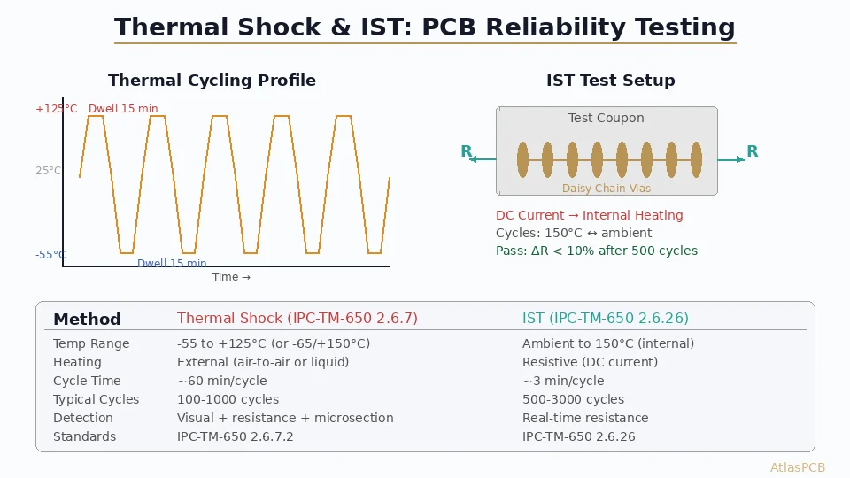
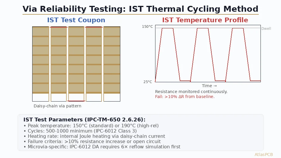
PCB reliability testing validates board performance under stress conditions including thermal cycling (-55°C to +125°C), vibration, humidity, and accelerated aging. Key tests include IST (Interconnect Stress Test), thermal shock, microsectioning, and solder float testing per IPC-TM-650.
Reliability testing ensures your PCB and assembled product will perform correctly over its intended lifespan. By applying accelerated stresses, these tests reveal weaknesses that would otherwise appear as field failures months or years after deployment.
Why Reliability Testing?
- Field failures are expensive: Warranty costs, reputation damage, potential safety hazards
- Accelerated testing saves time: Months of field life compressed into days or weeks
- Design validation: Proves the design meets reliability targets before mass production
- Process monitoring: Ongoing testing ensures manufacturing consistency
HALT (Highly Accelerated Life Testing)
Purpose
Find the operating and destruct limits of a product by applying increasingly severe stress (temperature and vibration) until failures occur.
Process
- Cold step stress: Start at room temperature, decrease in 10°C steps until failure
- Hot step stress: Start at room temperature, increase in 10°C steps until failure
- Rapid thermal transitions: Cycle between discovered cold and hot limits
- Vibration step stress: Increase vibration in 5G steps (6-axis random vibration)
- Combined stress: Apply temperature extremes and vibration simultaneously
Key Outputs
- Operating limits: Temperature and vibration levels where the product can still function
- Destruct limits: Levels that cause permanent damage
- Design margin: Difference between operating limits and specification limits
- Failure modes: What breaks first and how — guides design improvements
Typical Findings
- Solder joint fatigue (cold temperature + vibration)
- Connector contact issues (vibration)
- Component derating violations (high temperature)
- Crystal oscillator frequency drift (temperature extremes)
HASS (Highly Accelerated Stress Screening)
Purpose
Screen production units to catch infant mortality failures before shipping to customers. Uses stress levels derived from HALT results.
Process
- Apply combined temperature cycling and vibration within discovered operating limits
- Typical profile: -40°C to +80°C rapid cycling + 10-20G random vibration
- Duration: 10-30 minutes per unit (production-compatible)
- Monitor product function during stress
Key Principle
HASS should precipitate latent defects without consuming product life. Stress levels must be below the destruct limits found in HALT but above normal operating conditions.
Thermal Cycling
Standard Test Profiles
| Standard | Temperature Range | Ramp Rate | Dwell | Cycles |
|---|---|---|---|---|
| IEC 60068-2-14 | -40 to +125°C | 10°C/min | 15-30 min | 500-2000 |
| JEDEC JESD22-A104 | -55 to +125°C | 10-15°C/min | 10-15 min | 500-1000 |
| Automotive (AEC-Q100) | -40 to +150°C | 10°C/min | 15 min | 1000-2000 |
What Thermal Cycling Tests
- Solder joint integrity (CTE mismatch stress)
- Via barrel cracking (Z-axis expansion)
- Delamination (moisture + thermal stress)
- Wire bond integrity
- Component-to-board attachment
Acceptance Criteria
- No open circuits or intermittent connections
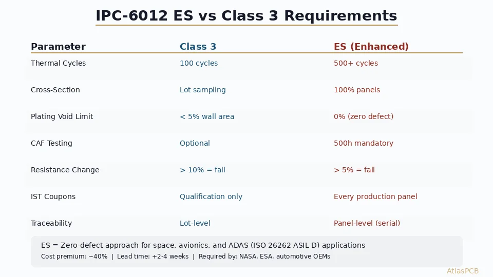
- Resistance change <10% (typically <5% for Class 3)
- No visible cracking under 10x magnification
- Cross-section analysis shows no micro-cracking
Vibration Testing
Random Vibration
- Simulates real-world vibration environment (transportation, operation)
- Frequency range: 5-2000 Hz
- Power spectral density (PSD) defined by application standard
- Duration: 30 minutes to 2 hours per axis (3 axes)
What Vibration Tests
- Solder joint mechanical strength
- Component retention (large capacitors, connectors)
- Wire/cable harness attachment
- Board mounting point stress
Humidity Testing
Steady-State Humidity
- 85°C / 85% RH for 500-1000 hours
- Evaluates moisture resistance of packaging and conformal coating
- Monitors insulation resistance between conductors
Temperature-Humidity-Bias (THB)
- 85°C / 85% RH with voltage applied
- Most severe humidity test
- Tests for electrochemical migration and CAF
- Duration: 500-1000 hours
Accelerated Life Testing
Arrhenius Model (Temperature Acceleration)
Product life at elevated temperature predicts life at normal temperature:
Acceleration Factor = exp[(Ea/k) x (1/T_use - 1/T_test)]
Where:
- Ea = activation energy (~0.7 eV for many failure mechanisms)
- k = Boltzmann constant (8.617 x 10^-5 eV/K)
- T = temperature in Kelvin
Example: Testing at 125°C for 1000 hours with Ea=0.7 eV approximates 15+ years at 40°C ambient.
Testing Strategy by Product Type
| Product | Key Tests |
|---|---|
| Consumer electronics | Thermal cycling (500 cycles), basic vibration, HALT (optional) |
| Industrial | Thermal cycling (1000 cycles), vibration, humidity, HALT |
| Automotive | Thermal cycling (2000 cycles), vibration, THB, HALT, HASS |
| Medical | Thermal cycling (1000 cycles), humidity, HALT, accelerated life |
| Military/Aerospace | Full qualification per MIL-STD-810, HALT, HASS, burn-in |
Conclusion
Reliability testing is an investment that pays for itself by preventing field failures. HALT early in development reveals design weaknesses when they’re cheap to fix. Thermal cycling and vibration testing validate the design meets its reliability targets. HASS in production catches manufacturing defects before they reach customers. The cost of reliability testing is a fraction of the cost of a single product recall.
Further Reading
- [HDI PCB Design Guide: Stackup Rules, Via Structures & DFM Checklist]/blog/hdi-pcb-design-guide/)
- [PCB Manufacturer with Engineering Review: Why Human DFM Audit Matters]/blog/pcb-manufacturer-engineering-review/)
About AtlasPCB — We specialize in complex PCB manufacturing for HDI, RF, and high-reliability applications. Explore our aluminum and metal-core PCB services . Every order includes free engineering review. Get your quote.
Reviewed by AtlasPCB Engineering Team — IPC-certified manufacturing specialists with 15+ years of production experience in HDI, RF, and high-reliability PCB fabrication. Content based on factory floor data and real customer design reviews.
Frequently Asked Questions
What is IPC Class 3 reliability testing?
What is thermal cycling testing for PCBs?
How do I test PCB plating quality?
- reliability testing
- HALT
- HASS
- thermal cycling