· Thomas Webb · Engineering · 8 min read
Metal Core PCB (MCPCB) Design Guide
Comprehensive design guide for Metal Core PCBs (MCPCBs) covering aluminum and copper core substrates, dielectric layer selection, thermal resistance calculations, single-layer vs multilayer MCPCB architectures, and DFM guidelines for LED lighting, power converters, and motor drive applications.
Quick Answer
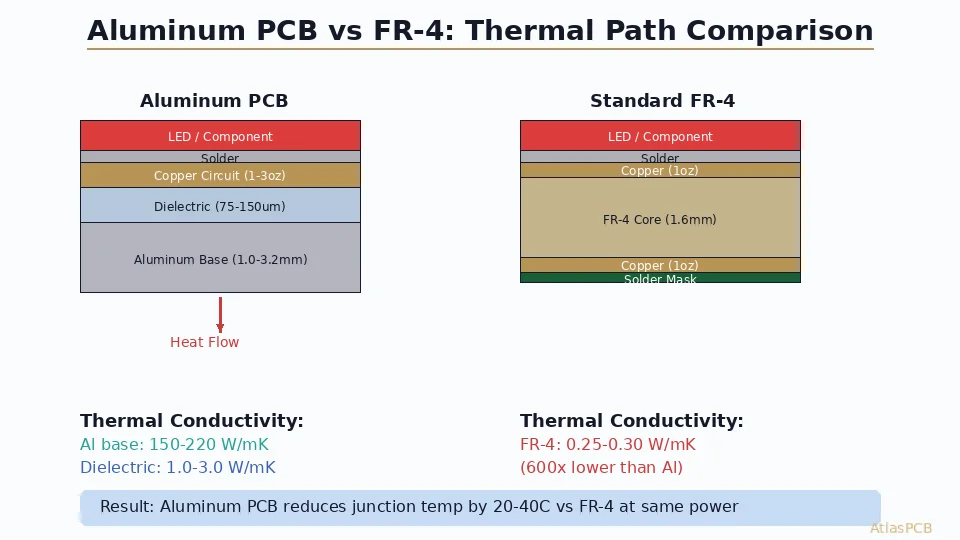
A Metal Core PCB (MCPCB) replaces the standard FR-4 substrate with an aluminum or copper metal base plate, providing 5–10× better thermal conductivity than organic laminates. The construction consists of a copper circuit layer, a thermally conductive dielectric insulation layer (1–3 W/mK), and a metal core that acts as both structural support and heat spreader. MCPCBs are the standard solution for high-power LEDs (reducing junction temperature by 20–40°C), power converters, and motor drives where effective thermal dissipation directly determines component lifetime and reliability.
Introduction: The Thermal Problem in Power Electronics
Every electronic component generates waste heat. For low-power circuits (microcontrollers, sensors, communication ICs), standard FR-4 PCBs dissipate heat adequately through copper planes and convection.
But high-power components create thermal densities that overwhelm organic substrates:
- High-brightness LEDs: 3–15 W per device, junction temperature must stay below 120°C for rated lifetime (50,000+ hours)
- Power MOSFETs/IGBTs: 10–500 W per device in motor drives and inverters
- Voltage regulators: 5–50 W switching converters in space-constrained designs
- RF power amplifiers: 10–100 W GaN/LDMOS devices for base stations
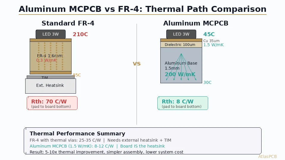
FR-4’s thermal conductivity is only 0.3 W/mK — acting as a thermal insulator rather than a heat path. Even with thermal vias (achieving equivalent conductivity of 2–4 W/mK in the via field), organic PCBs struggle to maintain acceptable junction temperatures for high-power devices.
Metal Core PCBs (MCPCBs) — also called Insulated Metal Substrates (IMS) — solve this by replacing the organic core with a thermally conductive metal plate, providing a direct low-resistance thermal path from the component to the heat sink.
MCPCB Construction
Single-Layer MCPCB (Most Common)
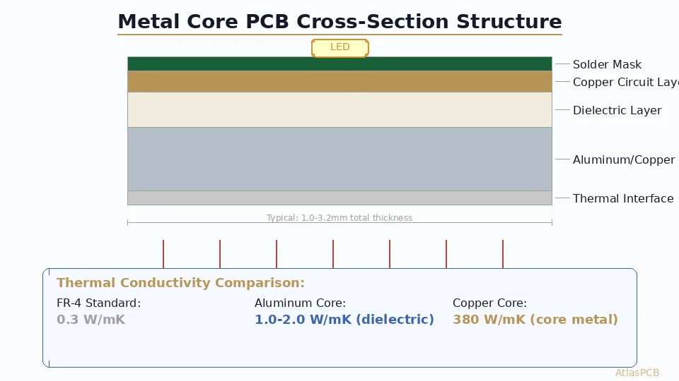
The standard MCPCB stackup from top to bottom:
- Solder mask (25–35 μm): Standard LPI solder mask, white for LED applications
- Copper circuit layer (35–105 μm / 1–3 oz): Standard etched copper traces
- Dielectric insulation layer (75–200 μm): Thermally conductive, electrically insulating polymer-ceramic composite
- Metal core (0.8–3.2 mm): Aluminum alloy or copper plate
- Optional: back-side finish: Anodization, plating, or thermal interface material pre-applied
The Dielectric Layer: Critical Bottleneck
The dielectric layer is simultaneously the most critical and most challenging component of MCPCB design. It must provide:
- Electrical isolation: 2–8 kV/mm breakdown voltage (safety requirement)
- Thermal conduction: 1–7 W/mK (performance requirement)
- Adhesion: Bond strength to both copper foil and metal core
- CTE compliance: Accommodate differential expansion between copper and aluminum
Standard dielectric formulations use epoxy or polyimide matrices filled with thermally conductive ceramic particles (Al₂O₃, BN, or AlN). Higher filler loading increases thermal conductivity but reduces breakdown strength and adhesion.
| Dielectric Grade | Thermal Conductivity | Breakdown Voltage | Typical Use |
|---|---|---|---|
| Standard | 1.0–1.5 W/mK | 4–6 kV/mm | General LED |
| Enhanced | 2.0–3.0 W/mK | 3–5 kV/mm | High-power LED, MOSFET |
| Premium | 3.0–5.0 W/mK | 2–4 kV/mm | Power modules, IGBT |
| Ultra-high | 5.0–7.0 W/mK | 2–3 kV/mm | Laser diode, CPV |
Metal Core Options
Aluminum alloys (most common):
- 5052-H32: Good thermal conductivity (138 W/mK), excellent corrosion resistance, standard for outdoor LED fixtures
- 6061-T6: Higher strength (276 MPa yield), machinability for CNC heat sink integration, 167 W/mK
- 1060 pure aluminum: Maximum thermal conductivity (234 W/mK) but softer — used for indoor applications without mechanical stress
Copper alloys (high-performance):
- C110 (ETP copper): 385 W/mK, for maximum thermal performance in power modules
- C194 (copper-iron alloy): 260 W/mK with superior mechanical properties for automotive
- CPC (Copper-Polymer-Copper): Sandwich construction reducing weight while maintaining thermal path
Thermal Analysis and Calculation
Thermal Resistance Model
MCPCB thermal performance is characterized by junction-to-ambient thermal resistance (θ_JA):
θ_JA = θ_JC + θ_CS + θ_SA
Where:
- θ_JC = Junction-to-case resistance (component datasheet value)
- θ_CS = Case-to-sink resistance (MCPCB contribution)
- θ_SA = Sink-to-ambient resistance (heat sink + convection)
The MCPCB’s contribution (θ_CS) consists of:
θ_CS = t_Cu/(k_Cu × A) + t_diel/(k_diel × A) + t_core/(k_core × A)
Where t = thickness, k = thermal conductivity, A = heat spreading area
Practical Example: 10W LED on MCPCB
For a 10W LED (4×4 mm thermal pad) on standard 1.6mm aluminum MCPCB:
- Copper layer (35 μm): θ = 0.035/(386 × 16×10⁻⁶) = 0.006 °C/W (negligible)
- Dielectric (100 μm, 2 W/mK): θ = 0.1/(2 × 16×10⁻⁶) = 3.1 °C/W (dominant)
- Aluminum core (1.5 mm): θ = 1.5/(167 × 16×10⁻⁶) = 0.56 °C/W
Total θ_CS ≈ 3.7 °C/W → With 10W dissipation, ΔT = 37°C across the MCPCB
Compare to FR-4 with thermal vias:
- FR-4 (1.6mm, effective 2 W/mK with via field): θ = 1.6/(2 × 16×10⁻⁶) = 50 °C/W
- ΔT = 500°C — catastrophically impossible!
This 13× improvement in thermal resistance is why MCPCBs are mandatory for high-power LEDs.
Heat Spreading Benefit
The metal core provides lateral heat spreading that significantly increases the effective heat transfer area. For a 4×4 mm LED pad on 1.5 mm aluminum, the heat spreads outward at approximately 45° through the metal core, creating an effective transfer area of ~100 mm² at the bottom surface (vs. 16 mm² at the component) — a 6× area multiplication that further reduces θ_SA.
MCPCB Manufacturing Solutions
AtlasPCB offers aluminum and copper core MCPCBs with dielectric conductivity up to 5 W/mK — optimized for your thermal requirements.
Design Guidelines for MCPCB
Copper Circuit Layer Rules
- Minimum trace width: 150 μm (6 mil) standard — wider than typical FR-4 minimum due to etching on thick copper
- Minimum spacing: 200 μm (8 mil) for 1 oz copper; increase to 300 μm for 2–3 oz
- Thermal pad design: Maximize pad area under power components; solder mask opening = component pad + 0.1 mm per side
- No through-holes to metal core: Standard MCPCBs are single-layer; if you need grounding to core, use dedicated “thermal via” structures (dielectric removed locally)
Dielectric Design Considerations
- Uniform thickness: Variation >±10% creates thermal hotspots and voltage withstand weak points
- Thermal via option: Some manufacturers offer “direct thermal path” technology — local removal of dielectric under thermal pads, with a thin metallization barrier providing minimal electrical isolation while maximizing thermal transfer
- Voltage isolation: For SELV (Safety Extra Low Voltage) circuits (<60V), standard 75 μm dielectric is adequate. For mains-connected circuits (>250V), specify 150+ μm dielectric with 4 kV Hi-pot test
Metal Core Thickness Selection
| Application | Recommended Core Thickness | Reason |
|---|---|---|
| Flexible LED strip | 0.8–1.0 mm aluminum | Bendability during installation |
| LED bulb/downlight | 1.0–1.6 mm aluminum | Standard, cost-effective |
| Street lighting | 1.6–2.4 mm aluminum | Structural rigidity, thermal mass |
| Power module | 2.0–3.2 mm copper | Maximum heat spreading |
| Automotive LED | 1.6 mm aluminum (6061-T6) | Vibration resistance |
DFM Best Practices
- Score-line routing preferred: V-score depaneling is standard for MCPCB arrays (tab routing generates aluminum burrs that cause electrical shorts)
- Board outline tolerances: ±0.2 mm (aluminum CNC routing), tighter than standard FR-4 (±0.15 mm)
- No plated through-holes: Standard single-layer MCPCB has no PTH capability. If through-board connections are needed, use pressed-in pins or rivets.
- Surface finish: HASL or OSP for LED (reflectivity matters); ENIG for fine-pitch power QFN packages
- Solder mask color: White for LED applications (95%+ reflectance improves luminaire efficiency by 3–5%)
Multilayer MCPCB Construction
For designs requiring signal routing complexity beyond single-layer capability, multilayer MCPCBs combine standard PCB layers with a metal core base:
2-Layer MCPCB:
- Layer 1: Signal/component copper (35 μm)
- Prepreg (standard FR-4, 100–200 μm)
- Layer 2: Ground/power plane (35 μm)
- Thermal dielectric (75–100 μm)
- Metal core (1.0–2.0 mm)
4-Layer MCPCB:
- Layer 1–4: Standard multilayer PCB stackup
- Thermal dielectric
- Metal core
The thermal penalty of multilayer construction: each additional prepreg/copper layer adds ~50 μm of FR-4-equivalent thermal resistance between power components and the metal core. Thermal vias through the organic layers partially mitigate this — achieving effective through-board conductivity of 10–20 W/mK in the via field.
Application Case Studies
High-Bay LED Luminaire (200W)
A typical 200W industrial high-bay light uses:
- 2.0 mm aluminum core MCPCB (6061-T6)
- 3 W/mK dielectric layer (100 μm)
- 50× 4W LED devices in 5×10 array
- White solder mask for maximum reflectance
- Mounting directly to die-cast aluminum heat sink housing
Thermal analysis shows junction temperature of 85°C at 50°C ambient — well within the LED manufacturer’s 105°C maximum for 50,000-hour lifetime rating.
Automotive IGBT Gate Driver (500V/50A)
Half-bridge motor drive for EV traction inverter:
- 3.2 mm copper core MCPCB (C110)
- 5 W/mK dielectric (150 μm for 2kV isolation)
- Power MOSFETs with exposed drain pad soldered directly to MCPCB
- 2-layer construction for gate drive routing on top + ground plane
- Operating temperature range: -40°C to +150°C
UV LED Curing System (395nm)
Industrial UV curing array for printing/coating:
- 1.6 mm aluminum MCPCB with mirror-finish white mask
- 36× UV LED devices (1W each, 395nm wavelength)
- Narrow 75 μm dielectric for minimum thermal resistance (UV LEDs are highly temperature-sensitive)
- Custom board outline matching reflector optics geometry
Testing and Quality Assurance
Standard MCPCB Tests
- Thermal resistance measurement (ASTM D5470): Verify dielectric thermal conductivity meets specification
- Dielectric breakdown voltage (IPC-TM-650 2.5.6): Hi-pot test at 2× working voltage + 1000V for 60 seconds
- Peel strength (IPC-TM-650 2.4.8): Copper-to-dielectric bond ≥1.0 N/mm (6 lb/in)
- Thermal cycling (IPC-TM-650 2.6.7): -40°C to +150°C, 1000 cycles, no delamination
- Solder float (IPC-TM-650 2.4.13): 288°C for 10 seconds, no blistering or separation
Common Failure Modes
- Dielectric delamination: Caused by moisture absorption + thermal shock; ensure dry-pack storage and pre-bake before assembly
- Copper lifting at pad edges: Over-etching undercuts the circuit layer; specify etch factor ≤3:1
- Core warpage: Asymmetric copper pattern creates CTE mismatch stress; balance copper area on board front/back
Further Reading
- Thermal Via PCB Heat Dissipation — Via-based thermal management for standard PCBs
- Heavy Copper PCB Design for Power Electronics — High-current PCB alternatives
- PCB Copper Weight and Thickness Guide — Copper thickness selection for current capacity
- PCB Reflow Soldering Profile Optimization — Assembly considerations for MCPCB
Ready to design your next MCPCB? Get a quote from AtlasPCB — we manufacture aluminum and copper core PCBs from prototype through high-volume production with thermal conductivity options from 1.0 to 7.0 W/mK.
About AtlasPCB — We specialize in complex PCB manufacturing for HDI, RF, and high-reliability applications. Explore our heavy copper PCB manufacturing, or get an aluminum PCB manufacturing . Every order includes free engineering review. Get your quote.
Reviewed by AtlasPCB Engineering Team — IPC-certified manufacturing specialists with 15+ years of production experience in HDI, RF, and high-reliability PCB fabrication. Content based on factory floor data and real customer design reviews.
Frequently Asked Questions
What is the difference between aluminum core and copper core MCPCB?
How thick should the dielectric layer be in an MCPCB?
Can MCPCBs have multiple copper layers?
- MCPCB
- metal core PCB
- thermal management
- LED PCB
- power electronics
- aluminum PCB
- copper core
- IMS substrate