· Priya Nair · Engineering · 7 min read
IPC-A-610 Acceptance Criteria
Master IPC-A-610 Class 1, 2, and 3 acceptance criteria for electronic assemblies. Learn inspection requirements, defect classifications, and how to specify the right class for your PCB assembly project.
Quick Answer
IPC-A-610 defines three product classes for electronic assembly acceptance: Class 1 (General Electronics) has the most lenient criteria suitable for consumer products, Class 2 (Dedicated Service Electronics) covers industrial and telecom equipment with moderate reliability requirements, and Class 3 (High-Performance Electronics) enforces the strictest criteria for aerospace, military, and medical life-support systems. The standard categorizes conditions as Target (ideal), Acceptable, Process Indicator (acceptable but warrants monitoring), and Defect (requires rework or reject). Most commercial electronics specify Class 2, which balances quality with manufacturing yield. Class 3 adds 20–40% to assembly cost due to slower production, 100% inspection, and higher rejection rates.
What Is IPC-A-610?
IPC-A-610, officially titled “Acceptability of Electronic Assemblies,” is the world’s most widely used standard for inspecting printed circuit board assemblies (PCBAs). Published by the Association Connecting Electronics Industries (IPC), this standard provides visual and dimensional criteria that inspectors use to determine whether an assembled board passes or fails quality requirements.
The standard covers every aspect of a finished PCBA: solder joints, component placement, mechanical assembly, cleanliness, coating, marking, and physical damage. With over 800 full-color photographs and illustrations across 450+ pages, IPC-A-610 serves as both a training document and an acceptance specification.
Current revision: IPC-A-610H (released 2024) with Amendment 1 (2025)
The Three-Class System
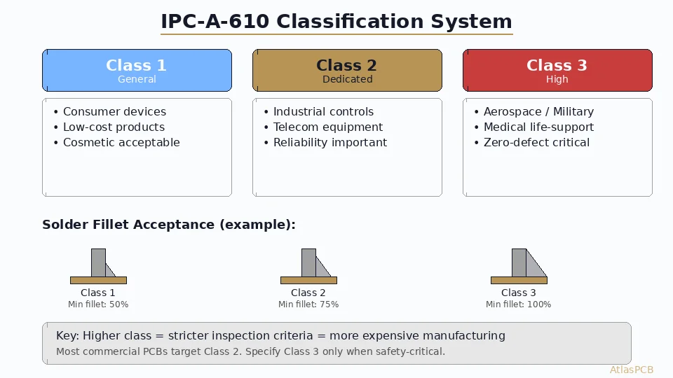
IPC-A-610’s classification system acknowledges that not all electronics require the same level of workmanship. A disposable calculator doesn’t need aerospace-grade solder joints. The three classes balance reliability requirements against manufacturing cost:
Class 1: General Electronic Products
Definition: Products where the primary requirement is function of the completed assembly.
Typical applications:
- Consumer electronics (remote controls, toys, basic IoT)
- Products with limited life expectancy
- Disposable or easily replaceable electronics
Key characteristics:
- Highest tolerance for cosmetic defects
- Solder joint criteria focus on electrical connectivity, not appearance
- Component misalignment tolerance is generous
- Surface cleanliness requirements are minimal
Example: A solder joint that has incomplete wetting on 50% of the pad is a defect in Class 3 but acceptable in Class 1 as long as electrical contact exists.
Class 2: Dedicated Service Electronic Products
Definition: Products where continued performance and extended life are required, with uninterrupted service desired but not critical.
Typical applications:
- Industrial controls and automation
- Telecommunications infrastructure
- Commercial/business electronics
- Automotive non-safety systems
- Test and measurement equipment
Key characteristics:
- Balanced quality/cost—the default for most professional electronics
- Solder joints must show good wetting with quantified fillet requirements
- Component placement tolerances are tighter than Class 1
- Cleanliness requirements per IPC-J-STD-001 or equivalent
- Statistical inspection sampling is acceptable
Class 2 represents approximately 70% of all electronic assemblies manufactured globally. When a purchase order doesn’t specify a class, most contract manufacturers default to Class 2.
Class 3: High-Performance/Harsh-Environment Electronic Products
Definition: Products where continued high performance or performance-on-demand is critical. Equipment downtime cannot be tolerated, equipment must function when required (e.g., life support, flight control).
Typical applications:
- Aerospace avionics and flight controls
- Military/defense weapons systems
- Medical life-support and implantable devices
- Space systems and satellites
- Nuclear plant controls
- Automotive safety-critical (ADAS, airbags, ABS)
Key characteristics:
- Most stringent requirements across all criteria
- 100% inspection mandatory (no sampling)
- Full traceability of materials and processes
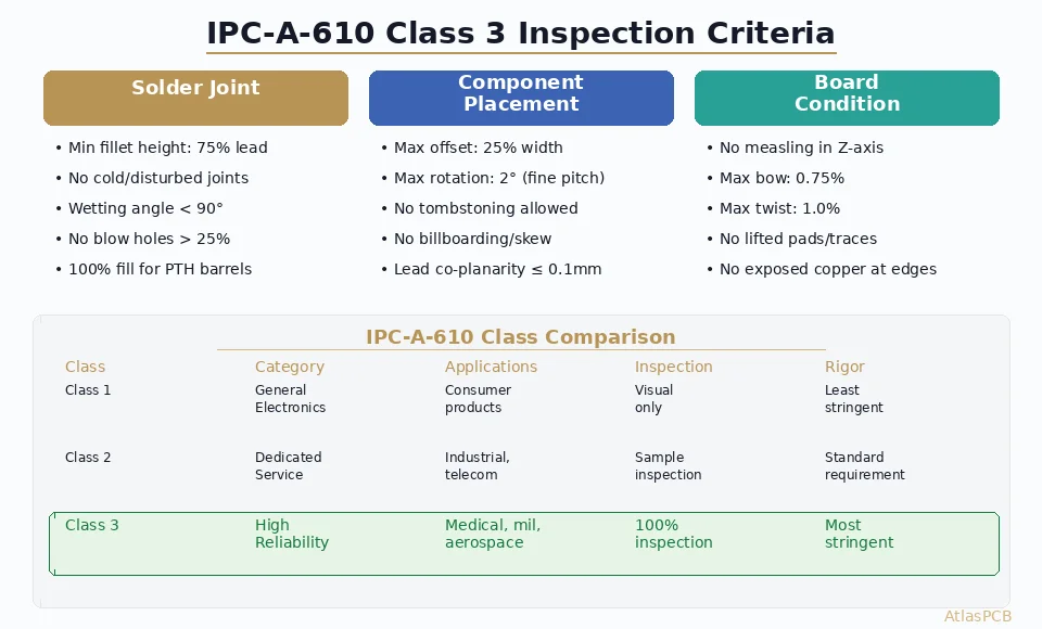
- Solder joints must demonstrate complete wetting
- Zero tolerance for most cosmetic defects
- Cross-section analysis may be required on test coupons
Condition Categories
Within each class, IPC-A-610 categorizes every observable condition into four levels:
| Category | Meaning | Action Required |
|---|---|---|
| Target | Perfect/ideal condition | None—this is the goal |
| Acceptable | Meets minimum requirements for the specified class | None—passes inspection |
| Process Indicator | Not ideal but doesn’t reduce reliability; indicates process could be improved | None required, but track for SPC |
| Defect | Does not meet acceptance criteria; likely to reduce reliability | Rework, repair, or scrap |
A condition that’s “Acceptable” in Class 1 may be a “Process Indicator” in Class 2 and a “Defect” in Class 3.
IPC-A-610 Certified Assembly
Class 2 and Class 3 Assembly Services
AtlasPCB assembly lines are IPC-A-610 certified with trained inspectors for Class 2 and Class 3 workmanship standards.
Get Assembly Quote →Critical Inspection Areas: Class 2 vs Class 3
Solder Joint Requirements
Solder joints represent the most frequently inspected feature. Key differences:
Through-Hole Solder Joints:
- Class 2: Solder fillet must wet at least 75% of pad on the solder-side, circumferential wetting not required
- Class 3: 100% circumferential wetting on solder side, fillet must fill barrel 75%+, visible wetting on component side
SMT Chip Components (0402–2512):
- Class 2: End overlap ≥50% of component metallization width; side overhang ≤50% of pad width or 0.5 mm
- Class 3: End overlap ≥75% of metallization; side overhang ≤25% of pad width or 0.25 mm
BGA Solder Joints:
- Class 2: X-ray inspection recommended; voids <25% of ball diameter acceptable
- Class 3: X-ray inspection mandatory; voids <10% of ball diameter; 100% ball inspection required
Component Placement Tolerances
| Component Type | Class 2 Tolerance | Class 3 Tolerance |
|---|---|---|
| Chip (0402+) | 50% max overhang | 25% max overhang |
| Chip (0201) | 25% max overhang | 10% max overhang |
| QFP leads | 50% off-pad | 25% off-pad |
| BGA | 25% offset vs ball | 10% offset vs ball |
| Connector | 1mm positional | 0.5mm positional |
Cleanliness Requirements
- Class 1: No specific cleanliness requirement unless customer-specified
- Class 2: Ionic contamination ≤1.56 µg NaCl eq./cm² (per IPC-TM-650 2.3.25)
- Class 3: Ionic contamination ≤0.78 µg NaCl eq./cm² or site-specific SIR testing
Physical Damage
- Class 1: Scratches through copper acceptable if circuit continuity maintained
- Class 2: Scratches may not expose copper; laminate damage limited to non-functional areas
- Class 3: No exposed copper; no measling or delamination; no damage to solder mask exposing base material
How to Specify IPC Class on Your Drawings
Proper callout on your assembly drawing ensures your CM knows the required class:
WORKMANSHIP: IPC-A-610, CLASS 2
SOLDERING: IPC J-STD-001, CLASS 2
For Class 3, add:
WORKMANSHIP: IPC-A-610, CLASS 3
SOLDERING: IPC J-STD-001, CLASS 3
INSPECTION: 100% visual + AOI, X-ray per BGA/QFN
TRACEABILITY: Full lot traceability per §1.6
Common Mistakes in Class Specification
- Specifying Class 3 “just to be safe”—adds significant cost with no benefit for non-critical products
- Not specifying any class—leaves quality expectations ambiguous; CM will default to Class 2
- Specifying Class 3 for bare board but Class 2 for assembly—creates a mismatch that confuses fabrication and assembly shops
- Citing an obsolete revision—always specify current (IPC-A-610H) or state “latest revision”
Cost Impact of Class Selection
| Factor | Class 2 (baseline) | Class 3 Premium |
|---|---|---|
| Assembly speed | Standard | −20% to −40% |
| Inspection coverage | AOI + sampling | AOI + 100% manual |
| Rejection rate | 2–5% | 8–15% |
| Documentation | Standard traveler | Full traceability pack |
| Rework allowance | Standard | Limited (some joints non-reworkable) |
| Total cost impact | Baseline | +20% to +40% |
Practical Tips for Design Engineers
Design for Class 3 Even if Specifying Class 2
The smartest approach: design your board with Class 3 layout rules (pad sizes, spacing, thermal relief) but specify Class 2 for manufacturing. This gives you:
- Higher manufacturing yield at Class 2 pricing
- Option to upgrade to Class 3 later without redesign
- Better reliability margins even at the lower class
Key Design Rules That Improve Any Class
- Generous pad sizing: Use IPC-7351B “Maximum (Most)” land pattern—gives inspectors clear visible fillets
- Thermal relief on all ground pads: Prevents cold joints from heat-sinking during reflow
- Testpoint access: Place test points per IPC-7351 for in-circuit test (ICT) fixturing
- Fiducial marks: Global + local fiducials improve placement accuracy
- Panelization margins: 5 mm rail minimum for AOI/inspection clearance
Training and Certification
IPC offers formal certification programs:
- CIS (Certified IPC Specialist): Entry-level inspector certification; 3-day course
- CIT (Certified IPC Trainer): Train-the-trainer; allows company to certify internal staff
- Recertification: Every 2 years with updated standard revision
Most contract manufacturers require all inspectors to hold current CIS certification for their production class level.
IPC-A-610 vs Related Standards
| Standard | Scope | Relationship to A-610 |
|---|---|---|
| IPC J-STD-001 | Soldering process requirements | Complementary—process vs. acceptance |
| IPC-A-600 | Bare board acceptance | Upstream—board quality before assembly |
| IPC-7711/7721 | Rework and repair procedures | Downstream—how to fix A-610 defects |
| IPC-6012 | Board performance specification | Bare board—different lifecycle stage |
Conclusion
IPC-A-610 provides the common language between designers, manufacturers, and customers for defining “good enough.” Understanding the three-class system allows you to specify the right balance of quality and cost:
- Class 1: When it just needs to work and cost is king
- Class 2: The sweet spot for professional electronics—quality without overkill
- Class 3: When failure is not an option and cost is secondary
The standard is not about perfection—it’s about fitness for purpose. Specify the class that matches your product’s actual reliability needs, design with generous margins, and communicate clearly with your CM.
Need IPC-certified assembly? AtlasPCB’s assembly facility maintains IPC-A-610H Class 2 and Class 3 certification with trained CIS inspectors on every line. Get your assembly quote →
Further Reading
About AtlasPCB — We specialize in complex PCB manufacturing for HDI, RF, and high-reliability applications. Explore our PCB assembly services, or get an full PCB manufacturing capabilities . Every order includes free engineering review. Get your quote.
Reviewed by AtlasPCB Engineering Team — IPC-certified manufacturing specialists with 15+ years of production experience in HDI, RF, and high-reliability PCB fabrication. Content based on factory floor data and real customer design reviews.
Frequently Asked Questions
What is the difference between IPC-A-610 and IPC J-STD-001?
How much does Class 3 inspection add to PCB assembly cost?
Can I specify different IPC classes for different areas of the same board?
- IPC-A-610
- PCB inspection
- quality control
- electronic assembly
- workmanship
- Class 3
- soldering standards
- PCBA