· Thomas Webb · Engineering · 6 min read
IPC-4101 Laminate Specification Guide
Complete guide to IPC-4101 laminate slash sheets for PCB designers. Covers material classification, key parameters (Tg, Td, Dk, Df, CTE, T-288), and selection criteria for high-speed, high-frequency, automotive, and aerospace applications.
Quick Answer
IPC-4101 is the base material specification for rigid and multilayer PCB laminates, using numbered 'slash sheets' (e.g., /99, /101, /126) to classify materials by their electrical, thermal, and mechanical properties. Each slash sheet defines minimum requirements for Tg, Td, CTE, Dk, Df, flammability, and moisture absorption, enabling designers to specify exact material performance without naming proprietary products.
Why IPC-4101 Matters for PCB Designers
Every PCB starts with a base material — the laminate and prepreg that form the structural backbone and dielectric layers of your board. While many designers simply specify “FR-4” on their fabrication notes, this generic callout encompasses a vast range of materials with dramatically different performance characteristics.
The difference between a bargain FR-4 (Tg 130°C, Td 300°C) and a premium high-speed laminate (Tg 200°C, Td 380°C, Dk 3.3 @ 10GHz) can mean the difference between a product that survives 1000 thermal cycles and one that delaminates at 200 cycles. IPC-4101 provides the framework to specify exactly what you need.
IPC-4101C (current revision) defines over 80 slash sheets covering:
- Standard and high-Tg epoxy glass (FR-4 family)
- Polyimide laminates (high-temperature)
- PTFE/ceramic composites (RF/microwave)
- Cyanate ester and BT blends (high-speed)
- Halogen-free formulations (environmental compliance)
- Metal-core and thermally enhanced substrates
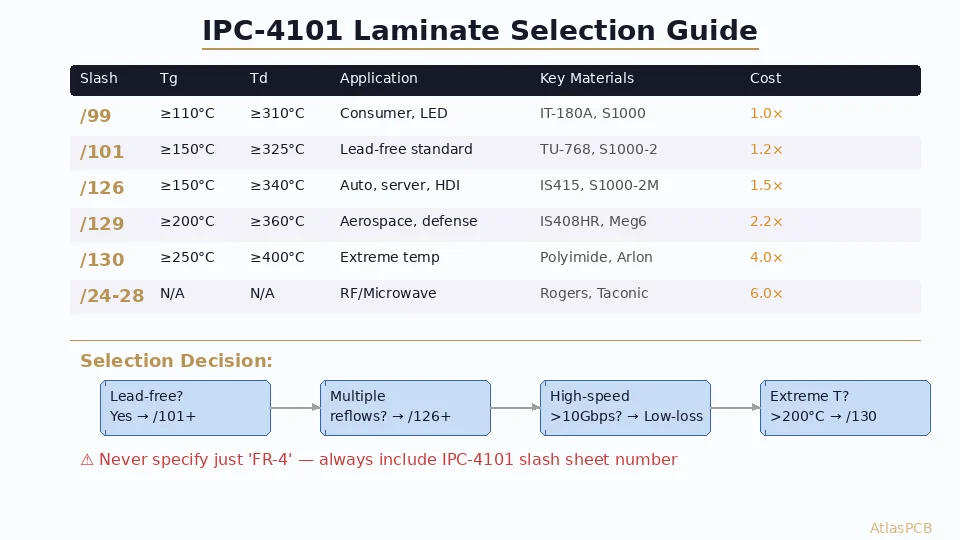
Understanding the Slash Sheet System
Structure of IPC-4101
Each slash sheet (designated as /XX or /XXX) defines a material category with:
- Reinforcement type (E-glass, S-glass, quartz, PTFE woven, non-woven)
- Resin system (epoxy, polyimide, PTFE, cyanate ester, PPE, BT)
- Key property minimums/maximums
- Test method references (IPC-TM-650 procedures)
The slash sheet does NOT specify a brand name. “/126” can be fulfilled by Isola IS415, Shengyi S1000-2M, Panasonic R-1755V, or any material meeting the published requirements. This enables competitive sourcing without sacrificing quality.
Most Common Slash Sheets for PCB Design
| Slash Sheet | Description | Typical Products |
|---|---|---|
| /21 | Woven E-glass / Epoxy, FR-4, Tg ≥ 110°C | Standard consumer PCBs |
| /24 | Woven E-glass / PTFE, Dk 2.1-2.4 | RF/microwave boards |
| /26 | Woven E-glass / PTFE, Dk 2.4-2.8 | RF/microwave boards |
| /97 | Ceramic-filled PTFE, Dk 3.0-3.5 | Antenna substrates |
| /99 | Woven E-glass / Epoxy, FR-4, Tg ≥ 110°C | Low-cost general purpose |
| /101 | Woven E-glass / Epoxy, Tg ≥ 150°C | Lead-free compatible |
| /121 | Woven E-glass / Epoxy, Tg ≥ 170°C | Multilayer, high reliability |
| /124 | Woven E-glass / Epoxy, Tg ≥ 150°C, Halogen-free | Eco-compliance |
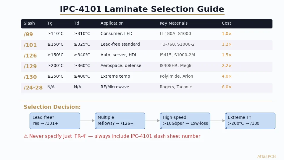
| /126 | Woven E-glass / Filled Epoxy, Tg ≥ 150°C, Td ≥ 340°C | Automotive, server |
| /129 | Woven E-glass / Filled Epoxy, Tg ≥ 200°C, Td ≥ 360°C | Aerospace, HDI |
| /130 | Woven E-glass / Polyimide, Tg ≥ 250°C | Extreme temperature |
Key Material Properties Defined
Glass Transition Temperature (Tg):
- Temperature where resin transitions from glassy to rubbery state
- Above Tg: CTE increases dramatically (z-axis expansion accelerates)
- Design rule: Tg should be ≥25°C above maximum sustained operating temperature
- Test method: DSC (IPC-TM-650 2.4.25) or TMA (2.4.24)
Decomposition Temperature (Td):
- Temperature at 5% weight loss (resin degradation onset)
- Critical for lead-free reflow survivability (peak ~245-260°C)
- Minimum for lead-free: Td ≥ 325°C; recommended ≥ 340°C
- Test method: TGA (IPC-TM-650 2.4.24.6)
Z-axis CTE (Coefficient of Thermal Expansion):
- Expansion in the thickness direction — stresses plated through-hole barrels
- Below Tg: typically 40-60 ppm/°C for FR-4
- Above Tg: can spike to 200-300 ppm/°C for standard FR-4
- Filled resins (/126, /129): 30-45 ppm/°C below Tg, <200 ppm/°C above
- Critical for thick boards (>2.0mm) and high-aspect-ratio vias (>8:1)
Dielectric Constant (Dk) and Loss Tangent (Df):
- Dk determines impedance and signal velocity
- Df determines signal attenuation (insertion loss)
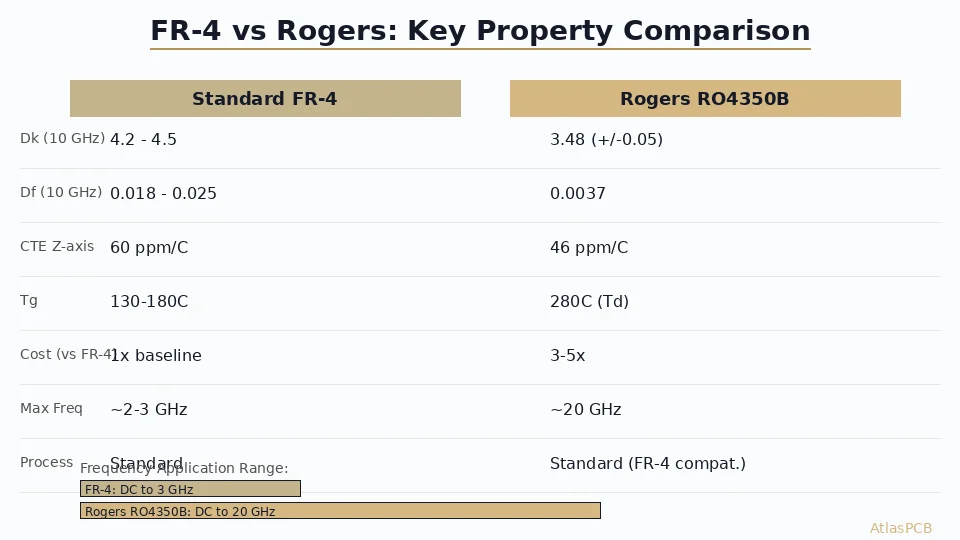
- Standard FR-4: Dk ~4.2-4.5, Df ~0.020-0.025 @ 1GHz
- Low-loss materials: Dk ~3.3-3.8, Df ~0.003-0.008 @ 10GHz
- Test method: IPC-TM-650 2.5.5.9 (stripline resonator) or 2.5.5.13 (split-post)
T-288 (Time to Delamination):
- Time the material survives at 288°C before delamination occurs
- Minimum for lead-free: >5 minutes
- High-reliability: >15 minutes
- Indicates thermal robustness during reflow and rework
- Test method: IPC-TM-650 2.4.24.1
Moisture Absorption:
- Weight gain after 24h immersion at 23°C (IPC-TM-650 2.6.2.1)
- Standard FR-4: 0.10-0.15%
- Low-moisture materials: <0.08%
- High absorption increases Dk and CAF risk
Material Selection Decision Tree
Step 1: Determine Operating Environment
| Application | Min Tg | Min Td | Z-CTE | Dk/Df Priority |
|---|---|---|---|---|
| Consumer electronics | 130°C | 310°C | <65 ppm | Low priority |
| Telecom/networking | 150°C | 340°C | <55 ppm | High (>10Gbps) |
| Automotive (under-hood) | 170°C | 350°C | <50 ppm | Medium |
| Aerospace/defense | 200°C+ | 370°C+ | <45 ppm | Application-specific |
| LED lighting | 130°C | 310°C | N/A | N/A |
| RF/microwave | Application | dependent | N/A | Critical (Dk tolerance) |
Step 2: Assembly Compatibility
Count the number of reflow cycles your board will experience:
- 1 reflow (single-side SMT): /99 or /101 adequate
- 2 reflows (double-side SMT): /101 minimum, /126 recommended
- 3+ reflows (rework, BGA reballing): /126 or /129 required
Lead-free reflow peak temperature considerations:
- SAC305: 245-250°C peak → Td ≥ 330°C with margin
- High-Ag SAC: 240-245°C peak → Td ≥ 325°C
- SnBi low-temp: 170-180°C peak → /99 adequate
Step 3: Electrical Requirements
For impedance-controlled designs:
- Standard digital (<1 Gbps): Any FR-4 is fine; use Dk 4.2 nominal
- High-speed (1-10 Gbps): Specify Dk tolerance ±5%; mid-loss (/126 class)
- Very high-speed (10-56 Gbps): Low-loss materials (Df <0.008); Megtron 6, Tachyon class
- RF/Microwave: PTFE-based (/24-/28) or ceramic-filled (/97); Dk tolerance ±2%
Step 4: Reliability Requirements
| Reliability Level | Recommended Slash Sheets | Typical Materials |
|---|---|---|
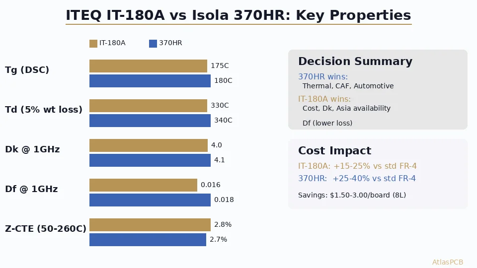
| Commercial | /99, /101 | IT-180A, S1000-2 |
| Industrial | /101, /121, /126 | IS415, S1000-2M |
| Automotive | /126, /129 | IS415, Megtron 6, R-5775K |
| Mil/Aero | /129, /130 (polyimide) | IS408HR, Arlon 85NT |
| Space | /130 + special qualification | Polyimide, CE/BT blends |
Need Help Selecting the Right Laminate?
AtlasPCB engineers review your stackup and recommend IPC-4101 compliant materials optimized for your performance, reliability, and budget requirements.
View Our Material Capabilities →Common Specification Mistakes
Mistake 1: Specifying Just “FR-4”
“FR-4” only guarantees UL 94V-0 flammability and woven E-glass/epoxy construction. It tells the fabricator nothing about:
- Tg (could be 130°C or 180°C)
- Td (could be 290°C or 360°C)
- CTE z-axis properties
- Lead-free reflow capability
- Electrical loss characteristics
Fix: Always specify IPC-4101 slash sheet number on your fabrication drawing.
Mistake 2: Over-specifying Material
Calling out Isola IS415 (or any proprietary name) when /126 requirements are sufficient creates:
- Single-source dependency
- Higher cost (no competitive bidding)
- Longer lead times
- Qualification risk if material gets discontinued
Fix: Specify the IPC-4101 slash sheet. Add “or equivalent” after a trade name if you must reference specific materials for qualification purposes.
Mistake 3: Ignoring Prepreg Compatibility
Mixing laminates and prepregs from different systems can cause:
- Delamination from resin incompatibility
- CTE mismatch stress between layers
- Unpredictable Dk profiles in the stackup
Fix: Specify that core and prepreg must be from the same material system or verify compatibility with the fabricator’s process engineer.
Mistake 4: Not Specifying Dk at the Correct Frequency
Material datasheets report Dk at 1 MHz, 1 GHz, or 10 GHz. These values differ significantly:
- Standard FR-4: Dk 4.7 @ 1MHz → 4.2 @ 1GHz → 4.0 @ 10GHz
- Low-loss: Dk 3.8 @ 1MHz → 3.5 @ 1GHz → 3.4 @ 10GHz
Fix: Specify Dk at your operating frequency. For impedance calculations, use Dk at the knee frequency of your signals (≈0.35 / rise time).
Practical Fabrication Notes
Material Availability by Region
Not all slash sheets have equal global availability:
| Region | Readily Available | May Require Lead Time |
|---|---|---|
| China/Asia | /99, /101, /126 | /129, /130 |
| North America | /99, /101, /121, /126, /129 | /130, PTFE |
| Europe | /101, /126 | /99 (less common), /130 |
For production volumes, discuss material availability with your fabricator during design phase — not after Gerber release.
Cost Impact
Relative cost multipliers (vs. standard /99 FR-4 = 1.0×):
| Slash Sheet / Material Class | Cost Multiplier |
|---|---|
| /99 Standard FR-4 | 1.0× |
| /101 Mid-Tg | 1.1-1.3× |
| /126 High-reliability | 1.3-1.6× |
| /129 Ultra-high performance | 1.8-2.5× |
| /130 Polyimide | 3.0-5.0× |
| Low-loss (Megtron 6 class) | 2.0-3.0× |
| PTFE (/24-/28) | 4.0-8.0× |
Specifying on Fabrication Drawings
Best practice format in your fab notes:
MATERIAL: IPC-4101/126, Tg ≥ 150°C (DSC), Td ≥ 340°C (TGA)
Dk: 4.0 ± 0.15 at 1GHz (reference stackup)
CORE THICKNESS: Per stackup drawing (tolerance ±10%)
PREPREG: Same material system as core
For critical designs, add:
T-288: > 15 minutes
Z-CTE: < 50 ppm/°C (below Tg)
MOISTURE ABSORPTION: < 0.12%
COPPER FOIL: RTF or STD profile per layer (see stackup)
Key Takeaways
- Always specify IPC-4101 slash sheet — never just “FR-4” on production drawings
- Match material to assembly process — lead-free requires /101 minimum; multiple reflows need /126+
- Consider the full property set — Tg alone doesn’t predict reliability; Td and z-CTE matter more for via survival
- Balance cost and performance — don’t specify /129 when /126 meets all requirements
- Verify availability early — exotic slash sheets may have 4-8 week lead times
Further Reading
- PCB Stackup Symmetry and Balanced Lamination for Warpage Control
- High-Frequency PCB Material Selection: Rogers vs PTFE
- HDI PCB Stackup Design: Advanced Configurations
AtlasPCB stocks a comprehensive range of IPC-4101 qualified laminates from /99 through /130, with fast-turn availability on high-reliability materials. Get a quote with guaranteed material traceability.
About AtlasPCB — We specialize in complex PCB manufacturing for HDI, RF, and high-reliability applications. Explore our impedance-controlled PCB manufacturing, Megtron 6 & 7 low-loss PCB manufacturing, or get an Isola 370HR high-Tg PCB manufacturing . Every order includes free engineering review. Get your quote.
Reviewed by AtlasPCB Engineering Team — IPC-certified manufacturing specialists with 15+ years of production experience in HDI, RF, and high-reliability PCB fabrication. Content based on factory floor data and real customer design reviews.
Frequently Asked Questions
What is an IPC-4101 slash sheet?
How do I choose between IPC-4101/99, /101, and /126 for my design?
Does IPC-4101 cover high-frequency RF materials?
- IPC-4101
- PCB laminate
- FR-4
- high-Tg
- base material
- PCB material selection
- prepreg
- high-speed PCB