· Thomas Webb · Engineering · 4 min read
Aluminum PCB for LED Applications
Learn about aluminum metal core PCBs (MCPCB) for LED lighting — structure, thermal conductivity, dielectric layer selection, design guidelines, and comparison with FR-4 boards.

Quick Answer
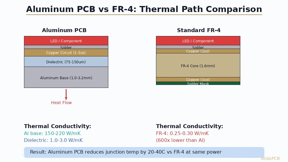
Aluminum PCBs (metal-core PCBs) use an aluminum base for superior thermal conductivity (1-3 W/mK vs FR4's 0.3 W/mK), making them ideal for high-power LEDs, power converters, and automotive lighting. The aluminum base acts as a built-in heat sink.
LED lighting is one of the fastest-growing segments in the electronics industry. LEDs convert 60-80% of electrical energy into heat, making thermal management the primary design challenge. Aluminum PCBs (MCPCBs) solve this problem with superior heat dissipation compared to standard FR-4 boards.
What Is an Aluminum PCB?
An aluminum PCB (also called Metal Core PCB or MCPCB) uses an aluminum alloy base plate instead of the traditional FR-4 substrate. The aluminum base acts as a built-in heat sink, efficiently conducting heat away from LED chips and other power components.
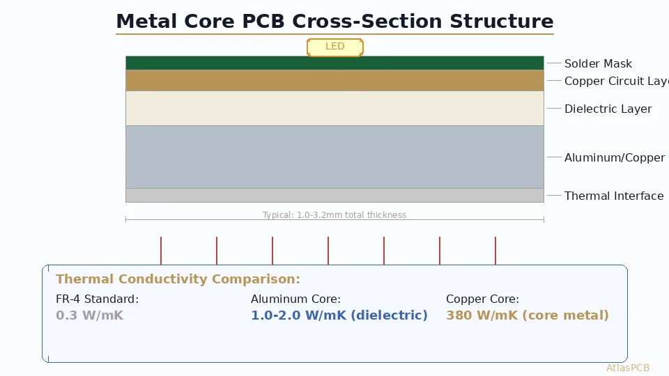
Structure (Bottom to Top)
- Aluminum base layer (0.8-3.0mm) — typically 5052 or 6061 alloy
- Dielectric insulation layer (50-200um) — thermally conductive but electrically insulating
- Copper circuit layer (1-4oz) — standard copper traces for circuit routing
- Solder mask and silkscreen — same as conventional PCBs
Why Aluminum for LEDs?
The Heat Problem
A 1W LED generates approximately 0.6-0.8W of heat. A 100W LED array generates 60-80W of heat. If this heat isn’t efficiently removed, LED junction temperatures rise, causing:
- Brightness reduction: Every 10°C above rated temperature reduces output by 3-5%
- Color shift: LEDs shift toward blue at higher temperatures
- Accelerated degradation: Lifespan drops exponentially with temperature
- Catastrophic failure: Junction temperatures above 150°C can permanently damage the LED
Aluminum PCB Thermal Advantage
| Parameter | FR-4 | Aluminum MCPCB |
|---|---|---|
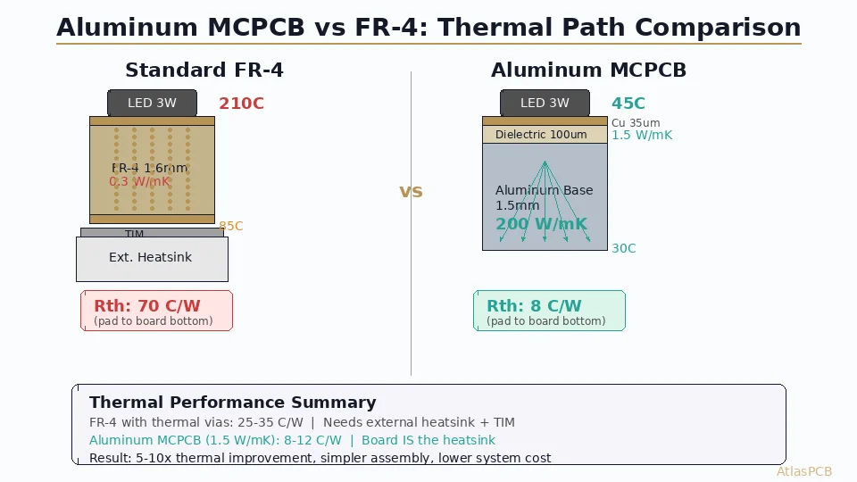
| Base thermal conductivity | 0.25 W/m·K | 150-200 W/m·K |
| Dielectric thermal conductivity | N/A | 1-8 W/m·K |
| Typical thermal resistance (board) | 20-80 °C/W | 0.5-5 °C/W |
| LED junction temp (same power) | 95-120°C | 55-75°C |
| LED lifespan impact | 25,000 hrs | 50,000+ hrs |
Dielectric Layer: The Critical Component
The dielectric layer is the most critical component of an MCPCB — it must be electrically insulating while being as thermally conductive as possible.
Thermal Conductivity Grades
| Grade | Thermal Conductivity | Typical Thickness | Applications |
|---|---|---|---|
| Standard | 1.0 W/m·K | 75-100um | General LED lighting |
| Enhanced | 2.0-3.0 W/m·K | 75-100um | High-power LED, automotive |
| Premium | 5.0-8.0 W/m·K | 50-75um | Extreme power, COB LED |
Key tradeoff: Higher thermal conductivity dielectrics cost more and may have lower breakdown voltage.
Electrical Properties
- Breakdown voltage: >3kV (standard), >5kV (enhanced)
- Dielectric constant: 4.0-5.0 typical
- CTI (Comparative Tracking Index): >600V for safety compliance
Design Guidelines for Aluminum LED PCBs
Copper Weight
- 1oz (35um) for standard LED circuits
- 2oz (70um) for high-current LED drivers
- Heavy copper (3oz+) rarely needed on MCPCB due to aluminum thermal conduction
Trace Width for LED Circuits
- LED forward current typically 350mA-1A per string
- 10mil (0.25mm) trace minimum for 350mA (1oz copper)
- 20mil (0.5mm) for 700mA
- 40mil (1mm) for 1.5A
LED Pad Design
- Thermal pad: Maximum copper area under LED
- NO thermal relief on LED thermal pads — direct connection to copper pour
- Solder mask opening: NSMD recommended for accurate LED placement
Board Dimensions
- Common shapes: round (COB spotlights), rectangular (linear fixtures), custom
- Aluminum can be easily routed, punched, or V-scored
- Standard thickness: 1.0mm (thin), 1.6mm (standard), 2.0-3.0mm (high-power)
Single-Layer vs Multi-Layer MCPCB
Single-Layer (Most Common)
- One copper circuit layer on aluminum base
- 90% of LED MCPCB applications
- Lowest cost
- LED driver components on the same side as LEDs
Double-Layer MCPCB
- Two copper layers with dielectric between them, on aluminum base
- Used when circuit complexity requires routing on two layers
- More expensive due to additional processing
- Thermal performance slightly reduced (two dielectric layers)
Hybrid Construction
- MCPCB for LED section + FR-4 for driver section
- Connected via board-to-board connectors or flexible cables
- Optimizes cost: expensive MCPCB only where thermal performance is needed
Aluminum vs FR-4 vs Copper Core
| Feature | FR-4 | Aluminum MCPCB | Copper MCPCB |
|---|---|---|---|
| Thermal conductivity | 0.25 W/m·K | 150-200 W/m·K | 385 W/m·K |
| Weight | Light | Medium | Heavy |
| Cost | Lowest | Medium | High |
| Machinability | Easy | Easy | Moderate |
| Layer count | 1-30+ | 1-2 | 1-2 |
| Best for | Low-power LEDs | Standard-high power | Extreme power |
Manufacturing Considerations
- CNC routing: Aluminum requires carbide tools; cutting generates heat and chips
- Drilling: Aluminum base doesn’t need plated through-holes (single layer), but pilot holes for mounting screws are common
- V-scoring: Standard V-score works well on aluminum substrates
- Surface finish: HASL or OSP most common for LED pads; ENIG for premium applications
- Solderbility: Same as FR-4 boards — standard reflow and hand soldering work
- Testing: Standard AOI and electrical testing apply
Cost Factors
| Factor | Impact |
|---|---|
| Aluminum thickness | 1.0mm cheapest, 3.0mm +30-50% |
| Dielectric grade | 1 W/m·K standard; 3+ W/m·K +40-80% |
| Copper weight | 2oz vs 1oz +15-20% |
| Board shape | Standard shapes cheaper; custom routing +10-20% |
| Quantity | Strong volume discounts above 100pcs |
Typical pricing (100x100mm round, qty 100):
- FR-4 1-layer: $0.30-0.50
- Aluminum MCPCB (1 W/m·K): $0.80-1.50
- Aluminum MCPCB (3 W/m·K): $1.50-3.00
Conclusion
Aluminum MCPCBs are the standard substrate for medium to high-power LED applications. Their superior thermal performance directly translates to brighter, longer-lasting, more efficient LED products. For most LED lighting designs, a single-layer aluminum MCPCB with 1-3 W/m·K dielectric provides the optimal balance of thermal performance and cost. Engage your MCPCB manufacturer early to select the right dielectric grade and aluminum thickness for your specific thermal requirements.
Further Reading
[ENEPIG vs ENIG: Which PCB Surface Finish for Your Design?]/blog/enepig-vs-enig/)
[PCB Surface Finish Guide: HASL, ENIG, OSP and More Compared]/blog/pcb-surface-finish-guide/)
[PCB Solder Mask: Types, Colors, and Functions Explained]/blog/pcb-solder-mask-guide/)
[PCB Thermal Management: Heat Dissipation Techniques for Reliable Electronics]/blog/pcb-thermal-management/)
[Heavy Copper PCB: Design Rules, Manufacturing Limits, and Thermal Management]/blog/heavy-copper-pcb/)
[IPC Class 3 Requirements: The Complete Guide for Designers]/blog/ipc-class-3-requirements/)
About AtlasPCB — We specialize in complex PCB manufacturing for HDI, RF, and high-reliability applications. Explore our aluminum PCB manufacturing . Every order includes free engineering review. Get your quote.
Reviewed by AtlasPCB Engineering Team — IPC-certified manufacturing specialists with 15+ years of production experience in HDI, RF, and high-reliability PCB fabrication. Content based on factory floor data and real customer design reviews.
Frequently Asked Questions
What is an aluminum PCB?
When should I use aluminum PCB instead of FR4?
- aluminum pcb
- LED pcb
- metal core
- thermal conductivity